This Tester is EOL (end of live)
Design to simulate pickup at different RPM to test TCI, CDI, Tachometers, Power valves and ignition coils.
And to extract the advance curve from a Digital TCI or CDI.
SIMULATION
- Range 1000 to 12000RPM in 12 steps.
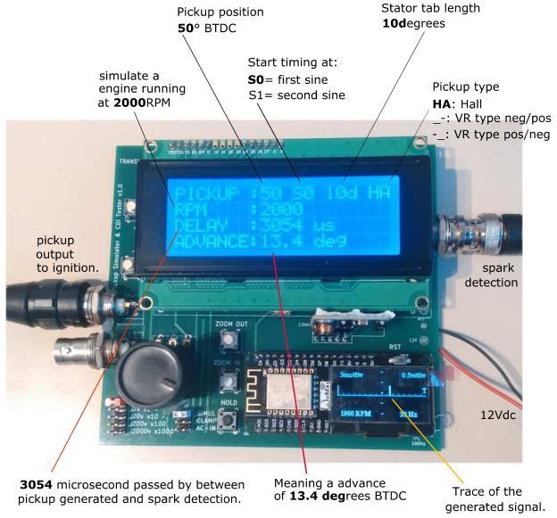
- Simulate a Hall sensor (square +12v signal). Adjustable width from 10 to 60 degrees.
- Imitate a VR (Variable Reluctance AKA Pickup coil) with both polarities: Positive than Negative or the opposite.
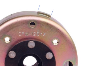
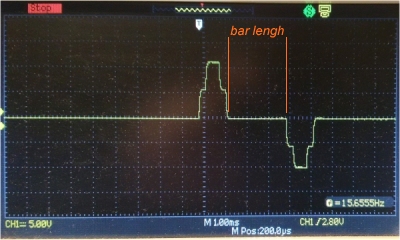
- Simulate a rotor bar length that define the delay between first and second sine.
The “length” is adjustable from 10 to 60 degrees.
|  |
ADVANCE DIAGNOSTIC.
The most advanced feature!
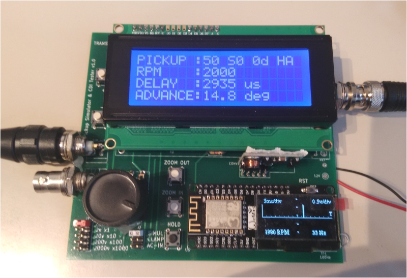
- With the help of a Capacitive Probe hooked to the sparkplug wire, this tester can time the duration between pickup and spark and display the advance timing of the TCI/CDI under test.
- The start of timing is selectable between First or Second sine.
- Detect RPM limiter
- Can test Digital CDI/TCI (with processor inside)
Cannot test simple analog CDI like GY6 (using only resistors and capacitors) as the advance timing comes mainly from the VR, not from those CDI.
OSCILLOSCOPE.
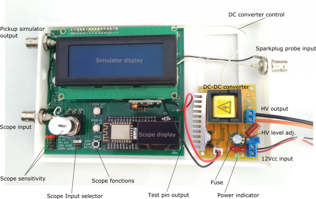
Tester comes along with a simple but useful one way scope!
- Display the pickup signal generated.
- Display the sparkplug signal captured by the capacitive probe.
- Can be used as a simple scope.
- AC Input from 2Vac until 2000Vac. AC only (no DC)
- Scope display voltage and time per division
- Automatic Frequency measurement
- RPM display.
- Display can be freeze with HOLD button in order to analyze, take photo, etc….
- A simple timebase is available to adjust Horizontal position from 0.7ms to 8ms/div
(Zoom IN & OUT buttons) - Automatic Trigger to stabilize trace.
- Persistence function to show random events or voltage/frequency changes
- Values display can be turned off
- Test pin puts out a 100Hz test square signal to test probe and scope.

Warning when applying high voltage:
The PCB ground will be connected to the voltage!
The board MUST be isolated (Use a plastic box)
DON’T touch the input selectors when applying voltage!
ALWAYS disconnect input BEFORE changing sensitivity jumpers.
HIGH VOLTAGE GENERATOR.
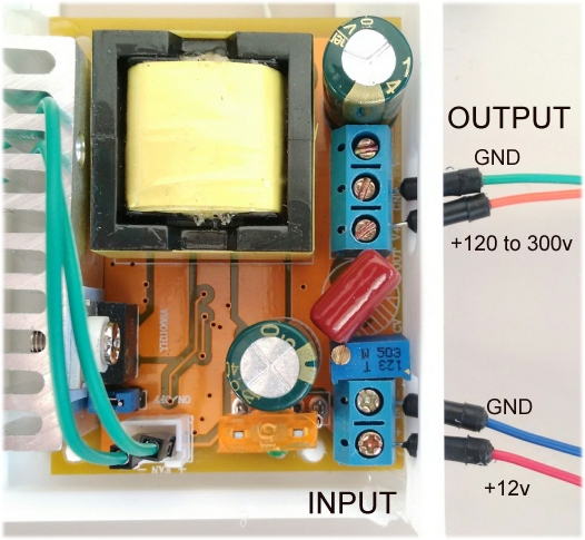
Needed to test AC-CDI boxes, this module generate 300Vdc from a 12Vdc battery.
- Output voltage manually adjustable from 100 to 390Vdc
- Output Power: 40W
- Current limiter (4.5A max)
- Short circuit protection
- Over Voltage protection (410v max)
- Conversion efficiency: 88%
PICKUP VOLTAGE.
The voltage produce to simulate a Hall or a VR pickup decrease with the load of the CDI under test.
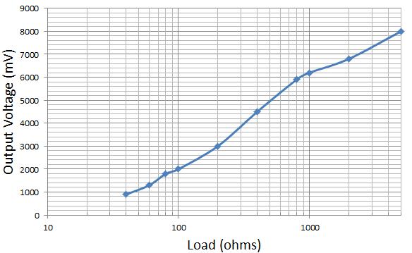
ie: if the input resistance of the CDI under test is 500ohm the generated pickup voltage is 5volts max.
Videos.
- How a pickup works?
- How to configure the CDI Tester?
Versionning.
-
- Version 4.0:
- Initial release as an upgrade of Simulator V3.
- Version 4.0:

Que precio tiene el probador de Cdi , tic?
Vivo en colombia, es posible enviarlo?
Hi,
It should be around 40€ for the KIT (PCB+programmed PIC+programmed Arduino+DC Converter)
and around 80€ built with High Voltage DC converter to test AC-CDI.
International tracking to Columbia cost around 10€
Cheers
(Please use English language)
Hi,
Great New tool you have developed. Congrats.
Can you put up a video here to see it working?
Need to discuss a different sort of rotor with 3 bar lengths. I had developed the TCI for It. But can we modify this tool /code to get exact timing data from that setup. Can send you pics of the rotor.
Bikram
Thanks Bikram.
I begun to add some videos on this page.
3 bars, I never saw that! Why 3 signals for a single cylinder?
Pictures alone don’t help. It you have photos + oscilloscope trace at a known RPM (ie: 2000rpm) I can have a look but honestly, it doesn’t worth it for me to spend days of coding for smth so specific and scarce…
Th
Hi, Thierry! I am using the same DC-DC module to make a CDI, however I need to interrupt the PWM at the moment of triggering the SCR, how did you do it? interrupted uc3843, lm393 or any other way? Thank you
Hi,
I drive pin 5 of LM358.
thank you! I have switched the jumper on / off of the board with NPN transistor, on my boards have the LM393 when I put 5v it fried :(. The way I did I was able to use the DC converter voltage control and reach up to 740 volts! continuous use and more than 20mj of power (capacitor charge) the ferrite transformer heats a lot :/
hi terry Is the CDI tester for sale?
Hi,
It WAS on sale but it’s now EOS (End Of Sale).
I’m currently developing a new version that will be still more accurate and powerful.
I hope to make it available in October 2019
Th