This Tester is EOL (end of live) and has been replaced by CDI Tester v6.2
Design to simulate pickup at different RPM to test TCI, ACCDI, DCCDI, Tachometers, Power valves and ignition coils.
And to extract the advance curve from a Digital TCI or CDI.
PICKUP SIMULATION
- Range 1000 to 24,000RPM in 24 steps.
- Simulate a VR (Variable Reluctance AKA Pickup coil) with both polarities: Positive than Negative or the opposite.
- Pickup “Position” relative to TDC is adjustable from 0 to 60 degrees BTDC.
- Simulate a rotor spoke length that define the delay between first and second pulse.
The “length” is adjustable from 0 to 45 degrees.

|  |
PICKUP VOLTAGE.
The simulated pickup signal is 30Vpp (+15v and -15v) or can be reduced to 20Vpp (+10v -10v) with jumper N°2.
If the CDI/TCI pickup input is highly capacitive, use jumper N°1 (L for Load) to connect a pull down resistor on the circuit.
PICKUP POLARITY.
|
Jumpers ON: 3 + 4: 1st N then P 5 + 6: 1st P then N 4 + 5: 1st N then N 6 : P 4 : N | 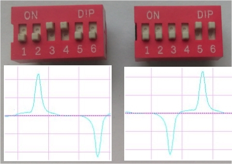 |
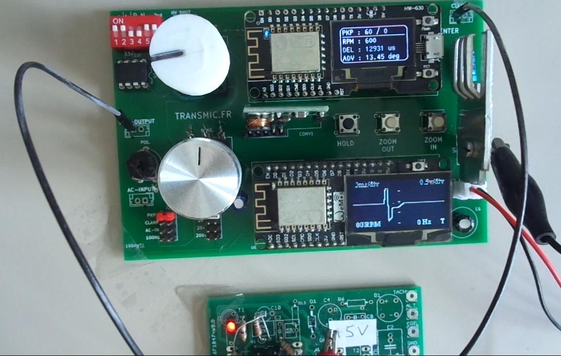
MEASURE ADVANCE TIMING.
The most advanced feature!
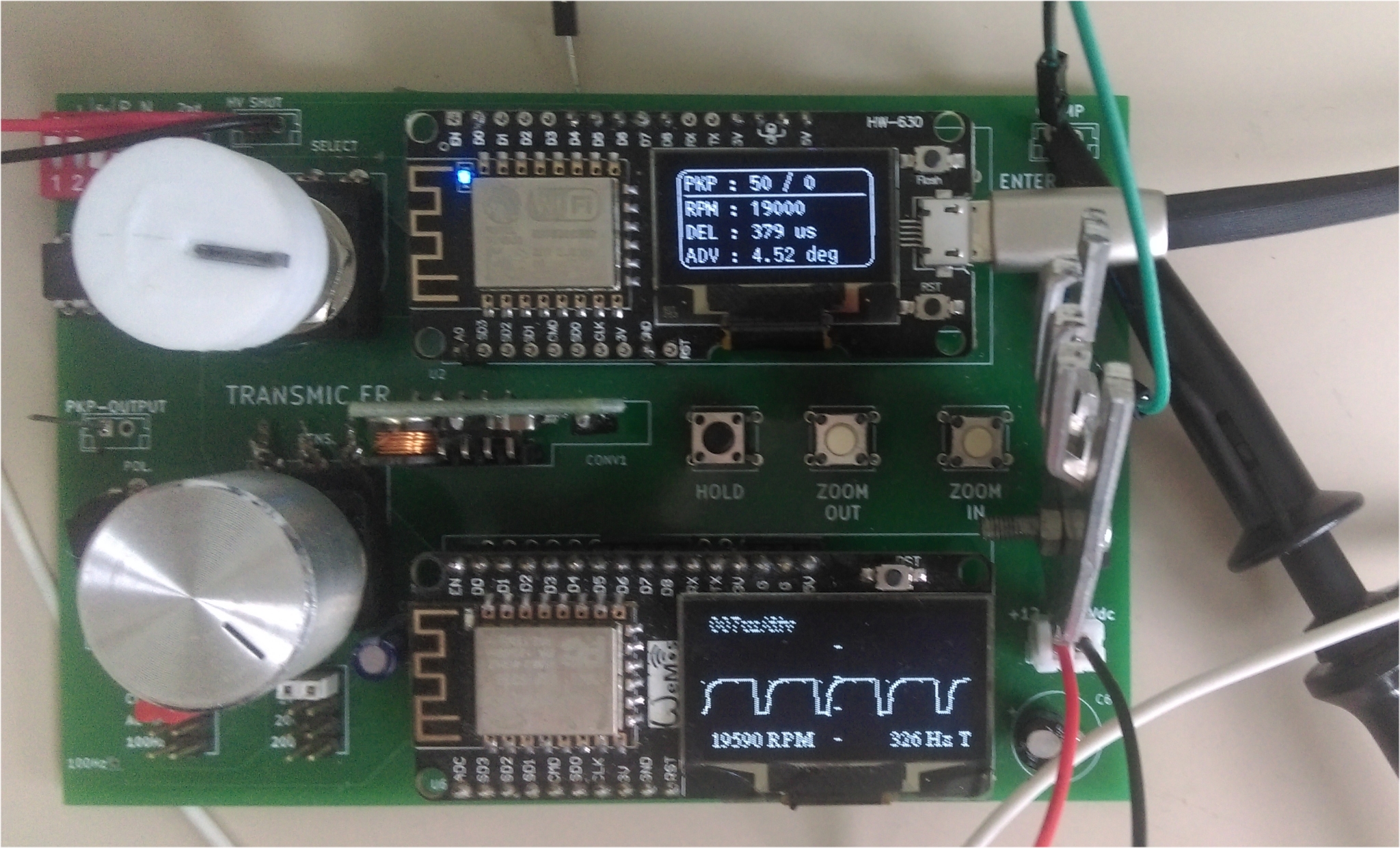
- With the help of a Capacitive Probe hooked to the sparkplug wire, this tester can measure the time that goes by between transmitted pickup and received spark and display the advance timing of the TCI/CDI under test.
To test ACCDI you will need an external High Voltage power supply (not provided). - During extraction, Advance timing is exported in CSV format on live via Serial USB at 115200-N-8-1
- Detect RPM limiter
- Can test Digital CDI/TCI (Electronic ignitions with processor inside.)
Cannot test simple analog CDI like GY6 (They only use resistors and capacitors and the advance timing comes mainly from the voltage of the VR, not from inside those CDI.) - Better accuracy is reached when WIDth is set to “0“.
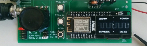
OSCILLOSCOPE.
Tester comes along with a simple but useful ONE WAY scope.
- Display the pickup signal generated.
- Display the sparkplug signal captured by the capacitive probe.
- Can be used as a simple scope (BW: 1KHz.)
- AC Input from 2Vac until 100Vac. AC only (no DC)
- Scope display time per division
- Automatic Frequency measurement.
- RPM display.
- Display can be frozen with HOLD button in order to analyze, take photo, etc….
- A simple timebase is available to adjust Horizontal position from 0.8ms to 80ms/div
(Zoom IN & OUT buttons) - Automatic Trigger to stabilize trace.
- Persistence function to show random events or voltage/frequency changes.
- Values display can be turned off.
- Test pin puts out a 100Hz test square signal to test probe and scope.
- Measure the Voltage of a signal.
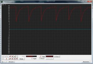
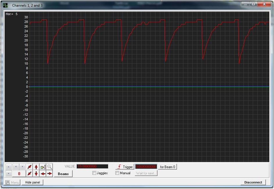
- View the scope on a PC.
With the help of “Serial oscilloscope” software, connect the scope to a PC and enjoy a big display and more functionalities:
(USB at 115200Kb, BandWidth:200Hz)
Warning when applying high voltage:
The PCB ground will be connected to the voltage!
The board MUST be isolated (Use a plastic box)
DON’T touch the input selectors when applying voltage!
ALWAYS disconnect input BEFORE moving jumpers.
HIGH VOLTAGE.
AC-CDIs need a charging coil that provide 100 to 300Volts.
No HV source is provided with this Analyser.
You can use the main power toward a isolation transformer (See Wiring).
But keep in mind the main frequency will limit the RPM reachable by the ACCDI.
(50Hz = 3000rpm max, 60Hz = 3600rpm max)
DOWNLOAD
| Parts list | Check voltage. | components placement old v4r3c1. | components placement new v4r3c2. | Connections for testing an ACCDI | Tester Setup |
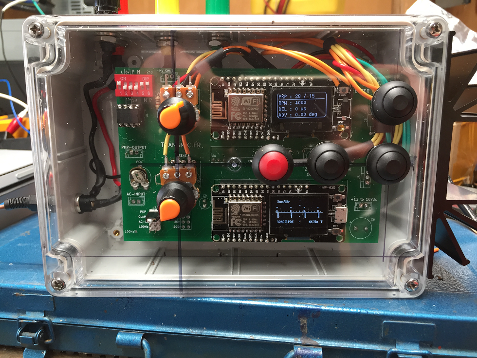
PHOTOS

VIDEOS
- How a pickup works?
Testing a Analog CDI (Not able to extract the advance timing as no proc inside.):
Scope the Analog CDI v2.4:
Why the tester shows: advance = -350°?
Minus sign mean that spark appear ATDC (After TDC) So it’s no more advance but it’s retard.
Extracting advance curve from a Digital CDI:
Versionning.
-
- Version v4r0:
- Initial release as an upgrade of CDI tester V3.
- 1000 to 10,000rpm
- Pickup position : 10 to 60deg BTDC
- Version v4r1:
- [soft] Upgrade : works from 1000 to 24,000rpm
- [soft] Pickup position : 0 to 60deg BTDC
- [soft] Export Advance timing in CSV
- Version v4r2:
- [hard] Divide power drain by 2. No more heatsink needed.
- [soft] Change in CSV export.
- [soft] Display advance in positive format.
- Version v4r3:
- [soft] Smaller pulses width at high rpm.
- [soft] Increased accuracy.
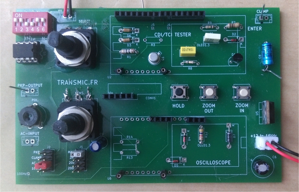
- Version v4r3c2:
- [hard] New PCB with SOP-9 print for U1.
- [hard] Radial capacitors.
- [hard] Add oscilloscope input protection.
- Version v4r0:
Apakah stok masih ada,bila ada lagi stok alat tes CDI? Harga alat tes CDI berapa?
is there still stock, CDI test kits
Today 2020/05/08 there is one Tester v4 available.
Let me direct your attention that it’s not a full kit. ONLY the main parts are provided and you must add other componants (resistors, connectors, capacitors etc)
You really did a great job Sir Thierry. I been a fan of yours since the day your website was up, and every time someone ask me about cdi, only your link and website is what I recommend for them to have a slight knowledge about CDI.
I didn’t attempt to enhance my knowledge with it, since I no longer interested in motorcycling due to poor standard here in my country, laws, safety, discipline of riders. and others.
I just want to congratulate your undying passion about cdi and hopefully soon you’ll have your own brand of CDI. Thank you.
Hi Nathaniel,
I truly appreciate your warming message!
I remember few years ago when we exchange info as you wrote for https://mastercircuits.blogspot.com/
I’m positive that you will sooner or later come back to own and tune your own motorcycle . Passion never vanish!
Hope the best for you
Good bye & take care
Th
Bonjour
Je souhaiterais construire un CDI pour un bicylindre 2 temps, j’ai pour idée d’utiliser votre AC-CDI V2.4 et de gérer l’avance avec une carte arduino (j’ai déjà presque finalisé le programme).
J’aurais également été interessé par votre CDI tester V4 mais apparemment il ne monte qu’à 10000 rpm, j’ai deux impulsions par tour et j’aurais donc pour 12000 rpm, 24000 impulsions par minute. Peut-on paramétrer le testeur pour simuler ça ?
sinon peut-on l’utiliser comme simple oscilloscope deux voies, auquel je connecterais mon capteur d’allumage et ma sortie arduino pour vérifier mon avance ?
Francis
Bonjour,
Si vous simulez le pickup avec un Arduino le signal sera donc toujours positif. Vous pouvez alors utiliser l’ancien ACCDI v2.2 (en plus je brade les PCB) car vous n’aurez pas besoin des DIP Switches.
J’ai regardé pour monter le CDI tester V4 à 24000 rpm, la génération du pickup fonctionne bien mais je me heurte a d’autres problèmes qui sont engendrés par cette augmentation.
Cela m’oblige a faire des modifs de code bien plus profondes… Pour l’instant j’essaye mais je ne promet rien!
C’est un oscillo UNE voie seulement (pin A0 de l’ESP) pas 2 voies. Je ne connais pas d’oscillo 2 voies très peu cher.
Par contre vous pouvez ruser en faisant une porte “ET” et envoyer sur l’unique voie:
– le signal de pickup a travers une diode.
– plus un peu de parasites du spark en enroulant un câble autour du fil de bougie et en le reliant également a l’entrée de l’osc.
Vous aurez les 2 signaux sur la même trace. C’est assez laborieux a faire mais je l’ai déjà fait a l’époque ou je n’avais pas d’oscillo 2 voies.
Cordialement
Th
J’ai essayé de commander le testerV4 et 4 cartes PCB V2.2 (j’ai plusieurs projets) mais je suis limité à 2.
Pour le tester si on peut monter à 20000 ce sera déjà suffisant,je ne suis pas pressé, je n’en ai pas besoin avant novembre.
Cordialement
Francis
J’ai monté la limite de PCB a 4 temporairement (3 PCB et + dépassent le poids d’une lettre de 20g).
J’avais la même demande d’upgrade du Testeur de CDI pour un 2temps j’ai donc bossé plein temps dessus et la version 4.1 disponible a partir de maintenant monte a 24.000rpm (trop de dégradation au-delà).
Il y a également une fonction supplémentaire d’export des valeurs en CSV.
Cdt
Th
commande passée. Je pense que 24000 suffira largement.
Cordialement.
Francis
buenas noches thierry buscando y buscando una solucion para mi moto acuatica de dos tiempos motor 800cc de 1996 su cdi o tci se averio y no consigo otro aca en peru y la verdad ya es mi ultima oportunidad en poder hacer funcionar esa moto quiciera encarecidamente que me ayudara a fabricar un cdi para mi moto que ya ace parada un par de años desde ya muchas gracias le envio el codigo 278-001-133 sea doo esperando su pronta respuesta.
Hi Julio
I’m honest with you: it will not be possible because you cannot communicate in English, wrote in the wrong page (tester instead of cdi), don’t know the type of ignition is on your engine, don’t give information on the engine…
To build an ignition is VERY complicated and you don’t seem to be an electronic guy!
No worries , I’m sure you are very good in other fields 🙂
But to guide me, to program the ignition and to wire it you MUST have STRONG knowledge of electronic, mechanic, have measurement instruments: multimeter, oscilloscope… All the electronics tools an electronic expert has!
You won’t find a direct replacement for 278-001-133 here, it’s a DIY (Do It Youself) website.
Regards
PS: it seem to be a DC-CDI
Hallo,
Graag zou ik de cdi tci scope willen bestellen.
Kunt u ook de rest van de componenten leveren?
Wanneer is de scope kit weer leverbaar?
Jos
Hello therry, a few years ago I saw your page, at that time it was the only one to build TCI-CDI and the operation of the same Asians as curves, build a CDI for a Chinese 200 cc motorcycle, it works well, without problem, Today I was in a WhatsApp group of a similar NX250 China that is marketed by Argentina with the name of Gilera G1, and we were talking about the CDI, which was better, as well as coil for the competition ism and there I remembered your page again , search my Gmail file until I have it again.
I see that it is modernized, with many new things, such as the CDI-TCI Tester, very good, that is what was missing, now I am interested in that tester, I wanted to know if you have stock and I send it to Arrgentina, CP2177 code greetings
Hi Luis,
I’m glad the CDI you build still works great after years !
The CDI/TCI Tester can extract advance timing from DIGITAL CDI only, boxes with processor inside. It can’t from analog CDI (like GY6)
This week I redraw the PCB. Next version wont have the scope display but will be smaller and have SMD parts already soldered. So it will be a easy kit to build.
I can now order 10 PCB to start with. Should arrive end of June
Here is the 3D vue:
No problem to send to Argentina but it’s long 3-4weeks..
Hello Thierry,
Any chance to purchase just the esp code and schematic? If would like to use your design inside a custom case; I don’t need the oscilloscope feature. I will design a custom pcb.
Thanks!
No problem. you buy the kit and put the ESP on your own board.
Why do you need the esp code for that?
Pls don’t take me for a fool!
Thierry,
My apologies if what I said came out wrongly. I have already bought your kit. 🙂
I was asking for a hex for like you have for the CDI boards. Not the source code.
Thanks!
Sorry then Madhu.
Sorry again I don’t sell the code (source or compiled) by itself. If you ordered (I don’t find your name in my DB) you’ve got the schematic.
Regards.
Thierry,
I had my friend order it for me. Ramachandra B G.
It was shipped to India.
Regards.
Madhu,
OK then. As there is no HEX for ESP, I can consider selling only the Oled ESP with Tester V4R3 firmware inside for 15€
Regards,
Thierry
Thierry,
I am sorry; but, my friend says he has not received the schematic in his email.
May I contact you for the schematic over email?
Thanks,
Madhu.
Hi Madhu , I have sent you both today the link by PM.
BR
Hello,
When you have the cdi scope back in stock?
Best regards jos
Hello
There will be 4 testers v4.3 available for the 20th of June, then another version v4.4 without scope but with SMD parts already soldered will take place in a month.
Regards,