Are the CDI of differents XT600 compatibles?
Until 1989, CDI of the XT550/XT600/SRX600/TT600 are electrically compatible but don’t have the same advance curve!
Although connectors, wiring and colors could be different with sometimes 2 or 3 more wires:
Blue: connected to ground when neutral.
Blue/yellow: connected to ground when side-stand in place (disconnected when sidestand open)
Sky-Blue: wire to neutral lamp (2KF wiring).
Since 1990 XT are fitted out with TCI.
TCI from models 3TB(electric start)/3UW/3UX/DJ02/4PT and SZR660/TT600e are compatibles.
| Year | Model | Ref | Ignition |
| 1982-1983 | XT125 | 12V/15E/15W/16A/17T/25A/2YE/3YU | ACCDI |
| 2005-2008 | XT125R | 5HH | DCCI |
| 2007-2008 | XT125X | 3D9 | DCCI |
| 2005-2006 | YBR125 | 3D9 | TCI or DCCDI? |
| 2007-2008 | WR125R – WR125X | TCI or DCCDI? | |
| 2005-2006 | YZF125R | TCI or DCCDI? | |
| 1977-1989 | DTMX125 | 2A6 | MAGNETO+Points |
| 1980-1986 | DTMX125 | 2A8 | ACCDI |
| 1986-1991 | DTMX125 | 3YV | ACCDI |
| 1982-1984 | XT200 | 15A,15X,15Y | ACCDI |
| 1982-1984 | XT240 | ACCDI | |
| 1980-1989 | XT250 | 3Y1/3Y3 | ACCDI |
| 1985-1995 | XT350 | 55V | ACCDI |
| 1981-1985 | XT400 | 5Y6 | ACCDI |
| 1978-1999 | SR400 | ACCDI | |
| 1985 | SRX400 | 1JL/3HU1 | ACCDI |
| 1988 | SRX400 | 2NY | ACCDI |
| 1991-1992 | XT400E | TCI | |
| 2000 | SR400 | TCI | |
| 1978-1999 | SR500 | 4F3/2J2/2J3/4E6 | ACCDI |
| 1978-1999 | SR500 | 48T/3EB | TCI |
| 1990-2002 | XT500E | TCI | |
| 1982-1983 | XT550 | 5Y1/5Y2/5Y3/28E | ACCDI |
| 1983-1984 | XTZ600 Tenere | 34L | ACCDI |
| 1985 | XTZ600 Tenere | 55W | ACCDI |
| 1986-1987 | XTZ600 Tenere | 1VJ | ACCDI |
| 1988-1990 | XTZ600 Tenere | 3AJ | ACCDI |
| 1984-1986 | XT600 | 43F/47N/49H | ACCDI |
| 1987-1988 | XT600 | 2KF/2NF/2WJ1 | ACCDI |
| 1987-1989 | XT600 | 2NF/2WJ2/3PW1/3PX1 | ACCDI |
| 1984-1987 | XT600 | 49M/49N/49R | ACCDI |
| 1988-1989 | XT600 | 2WK1/2WK2/3EN1 | ACCDI |
| 1990-1994 | XT600Kick | 3TBk/3UW | ACCDI |
| 1990-1997 | XT600E | 3TB/3UW/3UX/3UY/3WR | TCI |
| 1997-1999 | XT600E | VJ01 | TCI |
| 1999-2003 | XT600E | DJ02/4PT | TCI |
| 1990- | XT660 | TCI | |
| 1990- | XTZ660 | 3YF | TCI |
| 1994-1997 | XTZ660 | 4MY | TCI |
| 2004 | XTZ660 | 5VK1/DM011/1D21 | TCI |
| 2008-2016 | XTZ660 | DM02/11D/DM04/2BD/56P/2BE | TCI |
| 1983-1984 | TT600 | 36A | ACCDI |
| 1985-1988 | TT600 | 59X | ACCDI |
| 1989-1993 | TT600 | 3SW | ACCDI |
| 1991-1997 | TT600 | 55U | ACCDI |
| 1993-1995 | TT600S | 3TB | ACCDI |
| 1993-1997 | TT600S | 4LW/4GV | ACCDI |
| 1994-1998 | TT600E | TCI | |
| 1998-2002 | TT600R | DJ01/5CH | TCI |
| 2003-2005 | TT600RE | DJ01/5CH | TCI |
| 1994-2001 | TT600E | 4LW/4GV | TCI |
| 1986-1987 | SRX600 | 1XL/1XM/1XW | ACCDI |
| 1987-1988 | SRX600 | 2TM | ACCDI |
| 1996 | SZR660 | TCI | |
| 1994-1997 | MUZ,MZ660 | TCI? |
– Wiring to fit a 2KF CDI on a 55W bike:
- neutral contact (sky blue) connected to sky blue wire
- blue CDI wire connected to sky blue wire from tachometer
- blue/yellow CDI wire connected to ground.
What are the factory advance values?
by cc:
| Yamaha RD50LC | 7° at 1200rpm | |
| Honda MB5 50cc (1982) | 19° +or-3 > 3000tr/mn |
10° +or-5 > 7000tr/mn |
| Yamaha XT125 (55V/3YT) | 9° at 1300 à 2000rpm | 29° at 6000rpm |
| Yamaha TDR125 | 17° at 1700rpm | 23° at 4000rpm |
| Yamaha TTR125 | 6° at 1400rpm | ?° at 4000rpm |
| Yamaha RD125LC II | 16° @ 1300rpm | 30° @ 3000rpm |
| Yamaha DT125LC II | 8° @ 1350rpm | 30° @ 4000rpm |
| Yamaha TZR125 (2strokes) | 17° a 1500rpm | 28° a 4000rpm |
| Honda NSR F 125 – 1987/1998 | 24.3° at 3000rpm | |
| Yamaha RX135 (2strokes) | 3° a 1500rpm | 20° a 5000rpm |
| Suzuki DR200 SE | 7° at 1950tr/mn | 38° at 4400tr/mn |
| Honda XR250 | 8° at 1900tr/mn | 26-30° at 4300tr/mn |
| Yamaha XT250 | 7° a 1200 à 2000rpm | 32° a 4000rpm |
| Yamaha YP250 | 10° at 1500tr/mn | 32° at 5000tr/mn |
| Honda NX 250 – 1989 | 8° at 3000rpm | 30° at 4500rpm |
| Yamaha XT350 (55V/3YT) | 12° a 1200rpm | 34° a 5000rpm |
| Yamaha RD350LC | 17° at 1200rpm and 9000rpm | 27° at 3500rpm |
| Yamaha RD350LC 4L0 | 21° a 2000rpm | 27° at 3500rpm, 15° at 9000rpm |
| Suzuki DR350 | 5° < 2300tr/mn | 30° > 4300tr/mn (max 10500) |
| Honda CBR 400 RR – 1988/1995 | 18° at idle | 20° J-K models(?) 32° L,N,R models at 4500rpm |
| Honda XR400 | 8° at 1900tr/mn | 26-30° at 4300tr/mn |
| Yamaha XT400 (5Y6) | 12° à 1200tr/mn | 35° à 6000tr/mn |
| Honda XR500R | 6° at 1300rpm | 31° at 4000rpm |
| Yamaha SR500 | 7° à 1100tr/mn | 26,5° à 6000tr/mn |
| Yamaha XT500 (3EB) | 12° à 1200tr/mn | 34° à 6000tr/mn |
| Yamaha XT500 (48T) | 12° à 1200tr/mn | 27° à 6000tr/mn |
| Yamaha XT550 (2J4) | 12° à 1200tr/mn | 27° à 6000tr/mn |
| Yamaha XT550 (5Y3) | 12° à 1200tr/mn | 34° à 6000tr/mn |
| Yamaha XT600 (34L 43F) | 12° à 1200tr/mn | 36° à 4500tr/mn |
| Yamaha XT600 (3TB) | 12° at 1200 to 2700tr/mn | 28° at 6000tr/mn |
| Yamaha TTRE600 | 12° a 1300rpm | 31° a 7500rpm |
| Honda CBR 600 F – 1989/1990 | 15° at 1200rpm SW type 5° at 1400 rpm |
42° at 5500rpm |
| Suzuki DR600 | 0° < 2200tr/mn | 30° > 4300tr/mn |
| Honda XLV 600 H to T – 1987/1995 | 10° at idle | 30° at 4500rpm |
| Honda XLV 600 V to X – 1997/1999 | 10° at idle | 30° at 5000rpm |
| KTM 600 MX-EXC-EGS -1990 | 2° at idle | 30° at 5000rpm |
| Husqvarna TE610 (1997) PP33° | 09° at 2000rpm | 20° at 5000rpm |
| KTM 640 LC4 – 1999 | 38° at 6000rpm | |
| Honda XR650R | 6° at 1300rpm | 31° at 3500rpm 39° at 4000rpm |
| Suzuki DR650 | 0° < 2300tr/mn | 30° > 4500tr/mn |
| Aprilia Pegasso 655 (1995) | 10° at 2500rpm | 39° at 4000rpm |
| Yamaha XT660 (3YF 4BW) | 12° at 1300rpm | 38° at 6500rpm |
| Honda VFC750 | 10° at 1200tr/mn | 38° at 5500tr/mn |
| Suzuki DR800 | 5° < 2000tr/mn | 28° > 4300tr/mn |
| Yamaha TDM850 | 10° at 1300rpm | 42° at 5000rpm |
| Honda XLV1000 Varadero | 10° at 1200tr/mn | 45° at 4500tr/mn |
Please, give me the values you know to extend the list…
What if my pickup have only one output?
You can use the PIC CDI by connecting only the entry 36°.
Ignitions with one sensor use the negative wave from the pickup at kickstart and idle, and the positive wave for high revs.
The PIC based CDI does not use this negative shape so kickstarting will be thus harder.
I own a YaSuHonKa SX275R, will it works on my bike?
It impossible for me to answer, because you ask me to know the characteristics of YOUR motorbike!
As I cannot know electrical characteristics of thousands of models (that change every year), you must do this job of gathering information. First, carefully read the User Manual, the Service Manual and Google on Owner’s forums!
You should be able to answer those questions:
- How many strokes? (2 or 4)
- How many cylinders?
- How many ignition coil?
- What is the ignition type?
- Is it a TCI? (ignition coil connected to +12vdc battery)
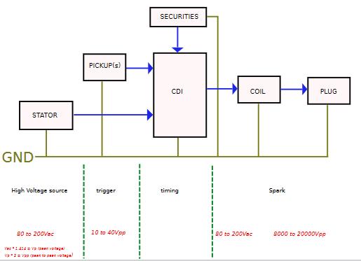
- Or is it a AC-CDI? (alternator provides 200Vac.)
- Or is it a DC-CDI? (Convert the 12Vdc battery into 200Vac)
- Or is it a MAGNETO?
- Pickup
- How many pickup are there?
- pickup type? (Hall, VR=analog coil?)
- How much voltage does it provide?
- How many pickup pulse per rotation? (one per rotation or missing teeth?)
- How is the pickup shape for VR type? (positive than negative or reverse?)
- How many degrees between pickup and TDC? (20degrees BTDC?)
- What is the ignition timing curve?
Does this CDI works on a twin?
It depend whether or not the Twin use a wasted spark!
On BMW twins, it works!
How to clean up the CDI?
The genuine PCB is embedded in a kind of resin that prevent vibrations, moisture… and reverse engineering!
To remove this mud: use 50% Dimethylsulfoxid (C2H5OS) and 50% Aceton (C3H6O)
Will I gain get extra power?
No. Yamaha’s engineers have the technological to get the maximum of power of their engine. If they were able to get 50 reliable HP,they would have done it… but you can modify the distribution of the power. (Ex: more advance = more torque at a particular rating) or remove the rev limiter.
Concretely, to get some extra power, you need to tune the advance curve according to the engine/exhaust/carburation/air filter mods.
A dyno bench is necessary then to compare different timing…
AC-CDI or DC-CDI?
TCI versus CDI
“TCI collapses an already charged coil by disconnecting it (TCI switches off briefly). These systems generally use a higher resistance
type coil and are known as an “induction” or “Kettering” ignition systems.
CDI sends a brief high (+200volts) voltage pulse to an uncharged coil which act like a transformer and multiplies it even higher.
The step up is normally around 100:1. These systems tend to use low resistance or “racing” oils.”
TCI is Not CDI
TCI and power transistor
The TCI of SR125 is fitted with a 2SD1071
(NPN Darl 6A/450V/40W/TO220 = BU806)
Spark coil for TCI/CDI
Usually CDI spark coil resistance are 0.2 to 0.5ohm/0.2 to 1mH whereas TCI spark coil resistance are 0.7 to 3ohm/4 to 8 mH.
4 cylinders
My CDI are for single cylinder: ONE pickup give the trigger signal, the cdi calculate the delay, and finally a high tension is send to ONE sparkplug coil
A 4 cylinders WITH a DELCO work the same: in this case, there is only ONE coil and the distributor connect the high voltage to each sparkplug, one after the other. The distribution is mechanical.
The CDI only see ONE coil, like a single cylinder (one pickup => one spark)
On new vehicles, there are 4 coils, one coil for each sparkplug, the distribution is no more mechanical but electronically driven meaning the CDI must provide 4 sparks (with good timing)
In this case, my CDI are not compatibles.
How to test the ignition system?
Always unplug the component before measuring its resistance!
Models with CDI
Ignition coil (Primary winding resistance) |
ground – orange |
to 2 ohm (125uH) |
Ignition coil (Secondary) |
Orange – spark plug |
|
Charge coil resistance (HV) |
Red – Brown |
|
batterie charging coil (LV) |
White – White |
0,23-0,38 ohm |
Pulser coil resistance |
Green – White/Red |
90-130 ohm |
Green – White/Green |
90-130 ohm | |
White/Red – White/Green |
180-260 ohm |
Models with TCI
Ignition coil (Primary) |
ground – Orange |
|
Ignition coil (Secondary) |
Orange – spark plug |
|
Pulser coil resistance |
184 to 276 ohm |
SR 500 Models CDI
| Ignition coil (Primary winding resistance) | 0,98 ohm |
| Ignition coil (Secondary) | 12 kohm |
| Charge coil resistance (HV) | 200 ohm |
| Battery Charging coil resistance (LV) | 0,8 ohm |
| Pulser coil resistance | 16 ohm |
| 87 ohm |
XT350 Models CDI
| Ignition coil (Primary winding resistance) | 0,79 ohm |
| Ignition coil (Secondary winding resistance) | 5,9Kohm |
| Charge coil resistance (HV) | 444 ohm |
| Battery Charging coil resistance (LV) | 0.46 ohm |
| Pulser coil resistance | 221 ohm |
XT225 Models CDI
| Ignition coil (Primary winding resistance) | 0,56-0,84 ohm |
| Ignition coil (Secondary) | 5,7Kohm-8,5kohm |
| Charge coil resistance (HV) | 584-876 ohm |
| Battery Charging coil resistance (LV) | 0.48-0.72 ohm |
| Pulser coil resistance | 656-984 ohm |
XT125 Models CDI
| Ignition coil (Primary winding resistance) |
1.6 ohm |
| Ignition coil (Secondary) | 6.6 Kohm |
| Charge coil resistance (HV) | |
| Battery Charging coil resistance (LV) | 4.5 ohm |
| Pulser coil resistance | 265 ohm |
TZR125 – TDR125 Models CDI
| Ignition coil (Primary winding resistance) |
0.6 – 0.8 ohm |
| Ignition coil (Secondary) | 5.7 – 8.5 Kohm |
| Charge coil resistance (HV) | 496 – 744 ohm Wt/Rd – Wt/Gr |
| Battery Charging coil resistance (LV) | 0.6 – 0.9 ohm |
| Pulser coil resistance | 280 – 420 ohm Wt/Rd-Wt/Bl |
Chinese 125cc pit bike CDI
| Ignition coil (Primary winding resistance) |
0.7 to 3 ohm (0.5 to 5) |
| Ignition coil (Secondary) | around 4 Kohm (3 to 12) Yl/Bk |
| Charge coil resistance (HV) | around 400 ohm Rd/Bk |
| Pulser coil resistance | 140 – 150 ohm Bl/Wt & Gn/Wt |
Troubleshooting an ACCDI
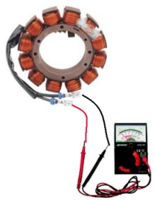
How to control a stator?
 |
|
- Look at the output AC voltage with a analog multimeter instead of a numeric one.
It’ll be more accurate and it’ll be easier to estimate how much is the peak voltage.
- Kick start the engine, you will get around 20Vac. The faster you kick, the higher tension you get.
- If the engine is idling, you will get around 50Vac until 150Vac at 5000RPM
How to control a ignition coil (CDI type) and spark plug?
 |
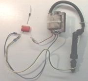 |
Load a 1uF or 2.2uF condensator on the main supply (110 or 220Vac) througt a diode, then connect the loaded condensator to the primary of the coil. A spark appears to the spark plug.
CAUTION: be careful because of the main power.
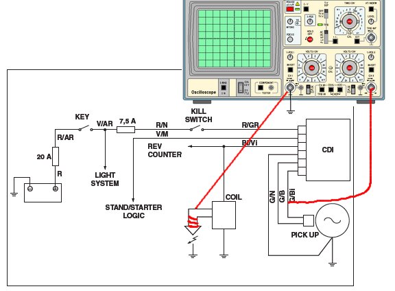
How to control a CDI?
You can control if the CDI provide sparks, you can also control the advance with a oscilloscope (first channel on pin 5, second on pin 7) by measuring the delay between input pulse and output spark.
If the delay is always the same at high and low RPM: the advance is out of order!
 |
1,2: High tension supplied by 2 small transformers 220v/9v, connected together by their SECONDARY, to produce a isolated tension for your security. 3: Input of the 12° sensor (unconnected). 4: Common of the sensors (connect to generator ground). 5: Input of the 36° sensor (connect to generator output). 6: ground (connect to ignition coil ground AND sparkplug ground) 7: Output to the spark coil (connect to ignition coil). |
The Low Frequency Generator simulate the signal of the pickups. One
can make change the frequency (16Hz to 116Hz equal 1000rpm to 7000rpm),
the tension, the shape of wave…
In this conditions, with a condensator of 1uF, the spark length in millimeters equal High_voltage divide by 13
ie: 260volts / 13 = 20mm spark length
How to extract the advance curve?
You will need:
– to know the exact position of the pickup.
– a working genuine CDI
– a oscilloscope (or a PC with sound card + oscilloscope software can do the job…)
- Measure the Delay (between pickup and spark) and Period (duration between 2 pickup pulses) values at differents RPM:
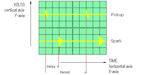
- Than use this excel sheet to convert your values to a rough advance curve.
Accuracy depend on how many measures you’ve done, and how precise there are…