How Yamaha’s CDI WORKS?

(Thanks to Mike and Gottfried who provide me with a “naked” CDI)
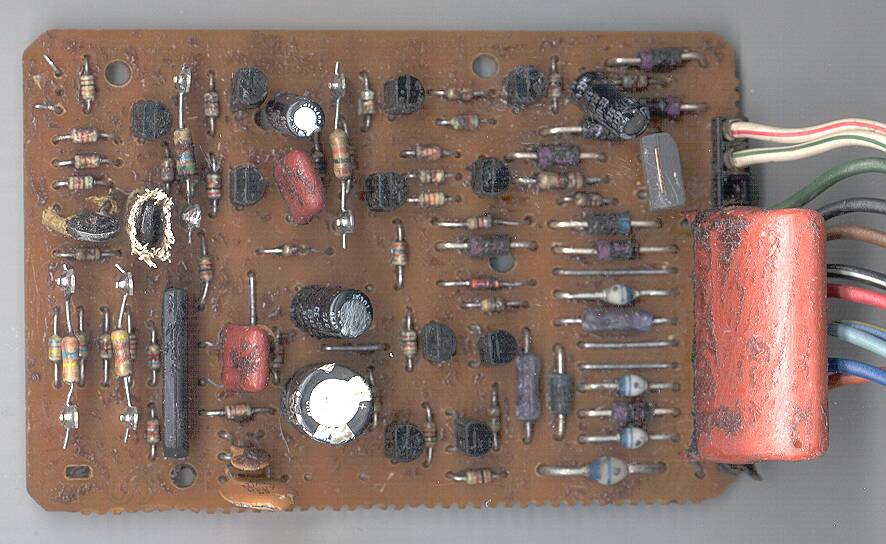
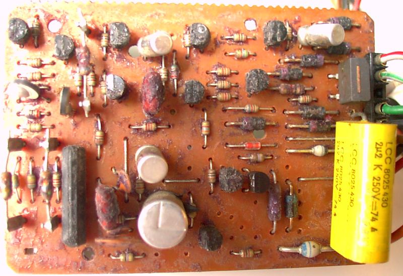
Description
In the cover of alternator is a dual pickup coil exciting by two metal stripes fixed on the flywheel.
Each time the stripe on the stator pass in front of a pickup, this one provide one pulse (at raising edge of the bump) followed by another pulse when the stripe leave the sensor (falling edge).
My CDI detect only a positive signal, so the very first pulse at rising edge MUST be positive (like Yam, Kawa)
If the positive shape is the latest at falling edge (like Honda and Suzuki), the timing will be wrong as my CDI will use a pulse that appear too late to get the max adv timing…
| Yamaha, Kawasaki Rising edge make a POSitive pulse and vice-versa |
Honda, Suzuki Rising edge make a NEGative pulse and vice-versa |
|  |
The tension of the pickup’s signal is proportional to the engine speed
The first sensor to be excited supplies pulses on the white/red wire with 36° advance.
A few millisecond later, the second sensor of the dual pickup to be excited supplies pulses on the white/green wire with 12° advance.
This two sensors produce alternatives pulses. (goes from ±2v while kick-starting to ±10v at low RPM until ±20v at high RPM)
The green wire is the common point of these two sensors.
While kickstarting and when pickups are disconnected from the CDI, the pickup provide ±2volts :
At starting of the engine, the pulses of the 1st pickup (White/Red at 36°) are blocked.
Only the pulses of the 2nd pickup (White/Green at 12°) are used to obtain 12° advance and not risk a kick back.
At idle and low revs, pulses from the 1st sensor at 36° are so delayed that they don’t have time to trigger the SCR.
Only the 12° is then used.
At mid revs, pulses from the 12° pickup loads a resistor + capacitor cell to get a Frequency to Tension conversion. (the more the rpm, the more the tension.)
This resulting tension is used by a monostable circuit to delay pulses coming from the 1st pickup (36°).
The more the revs raises, the less is the delay and the sooner is the spark until it comes before the spark triggered by the 12° pickup.
At high RPM then the SCR is triggered 2 times: First by the 36° pickup resulting in a spark then later on with the 12° pkp not resulting in a spark as the main capacitor is still empty.
At 1000RPM:
at 4000RPM:
(c) http://m.bosson.free.fr/SRX/CDI/C.D.I._SRX.html
Schematic
(Thanks to Gottfried for this draft)
Synoptic
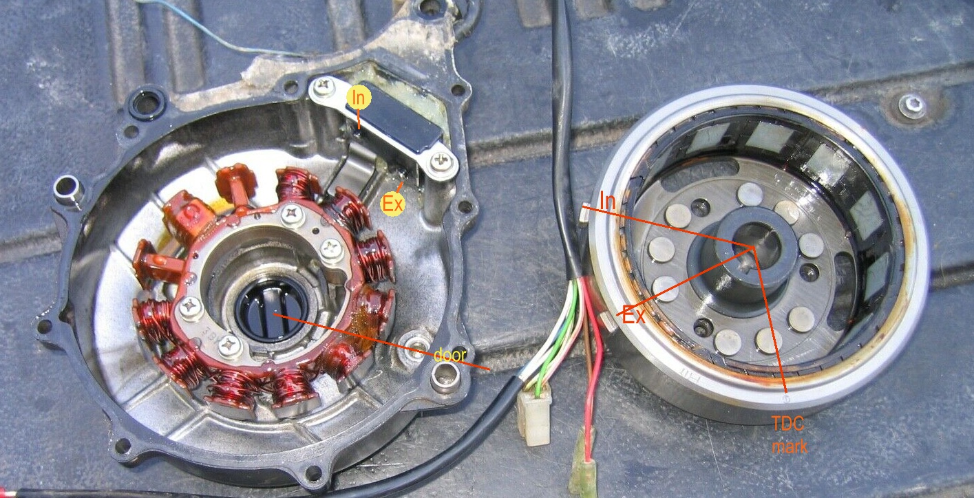
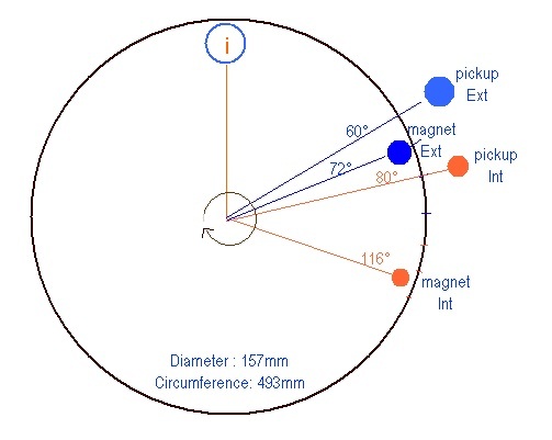
Internal pickup = 116° – 80° = 36° BTDC
External pickup = 72° – 60° = 12° BTDC
Best Explanation !
Really helpful, thanks for the hard work in creating the descriptive schematics and explanation.
What does SCR stand for?
Thanks ! I appreciate;
SCR for Semi Controlled Rectifier, it’s simply a Thyristor.
Interesting!
i have a 1994 xtz 660 with a sick ignition. At this date, no spark at all. My “CDi” has 8 connectors. Is it possible to adapt one of the described units to my machine? I don`t know the advance values for my machine. Anyone done this adaption?
Hi,
Check out the reference of your bike in the FAQ section but I think that since 1990 it’s a TCI and not a CDI. Then you can’t adapt a CDI as it’s a different hardware and software.
Hi
I have a xt 400-82.
does the cdibox from any other machine fit´ts my one. xt 550 or xt 600(what year?
Hi
I have a xt 400-82.
does the cdibox from any other machine fit´ts my one. xt 550 or xt 600(what year?
Hi
If you had read the FAQ you would know that XT400 and XT550(5Y3) share the same curve.
Then you can “certainly” swap their CDI
FAQ:
https://transmic.net/index.php/2016/07/02/faq/