This Tester is EOL (end of live) and has been replaced by CDI Tester v6.2
As a result all firmware (versions 2.3, 3.3, 3.4, 3.5) are now FREE!
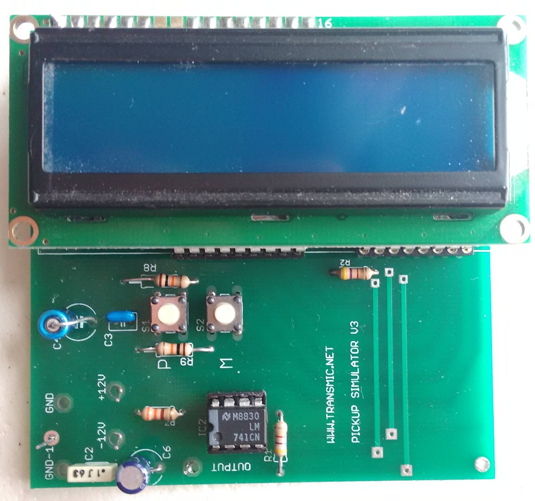
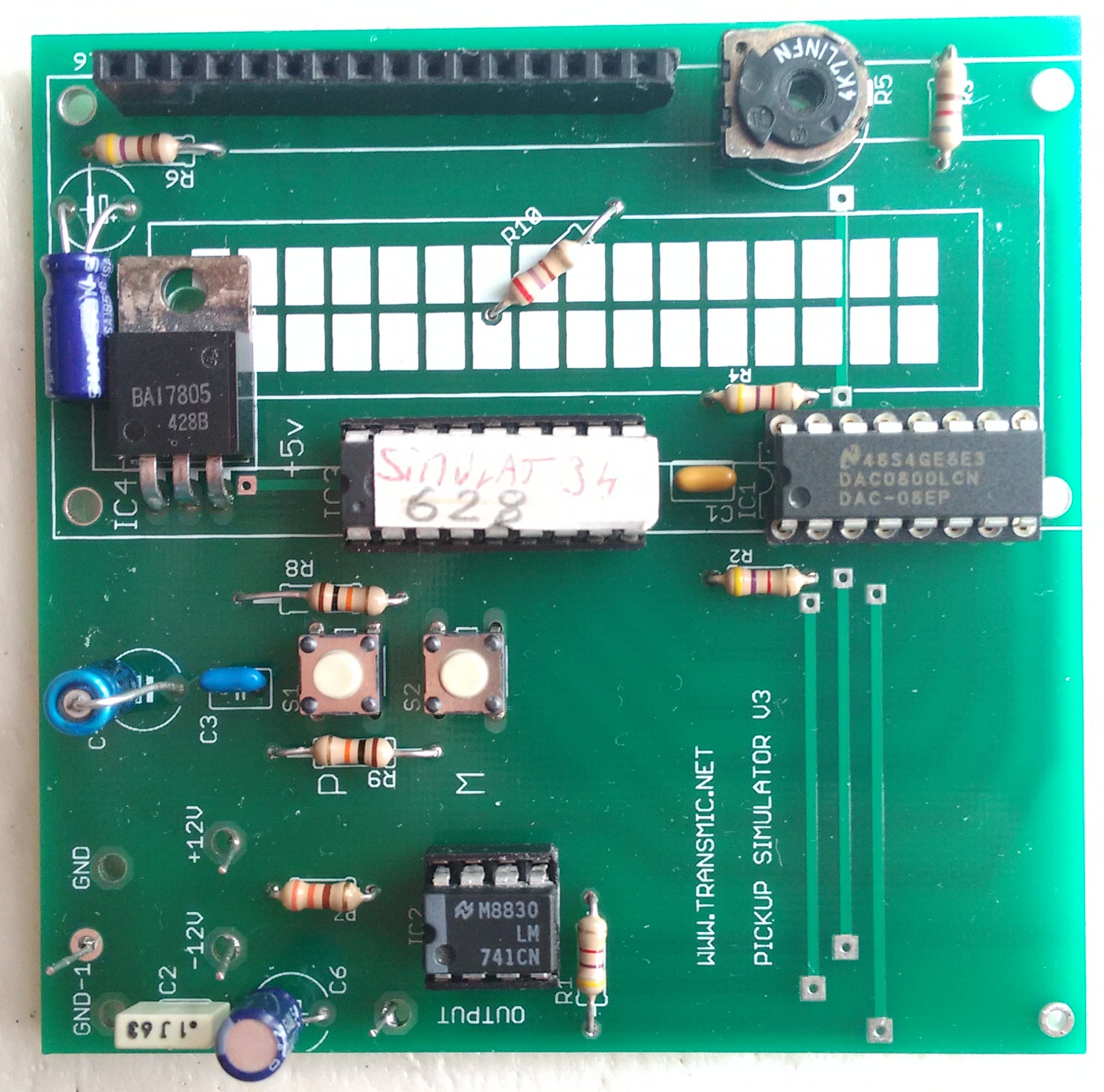
Design to simulate a pickup coil at different RPM to test CDIs, Tachometers, Power valves and ignition coils.
Range: from 300 to 30000 RPM (V2.x)
Range: from 1000 to 30000 RPM (V3.3)
Download.
| Simulator v2.3 | Software | Schematic | Parts list | Circuit board | Eagle files | PIC-LCD-DAC pinouts |
| PIC 16F628A | .HEX | .TXT | .PDF .JPG |
.SCH .BRD | .TXT LCD datasheet |
Version 2.3 is free to use.
Software versions 3.3, 3.4, 3.5 are only available for sale into the SHOP.
Versions 3.3, 3.4, 3.5 are available for FREE into the SHOP.
Checksum v2.3: 16F628A Checksum: 400D
Configuration word: PICKIT3: 2100h (xx1x xxx1 0001 0000b)
ICPROG : 3F10h (0011 1111 0001 0000b)
Checksum v3.3: 16F628A Checksum: D581
Configuration word: PICKIT3: 2100h (xx1x xxx1 0001 0000b)
ICPROG : 3F10h (0011 1111 0001 0000b)
Checksum v3.4: 16F1847 Checksum: EBDC
Configuration word: 3E04
Checksum v3.5: 16F1847 Checksum: 3F69
Configuration word: 3E04
How does it work?
Polarity
When LCD is displaying:
Pickup type : ?

-_     or     _-
then select:
- Plus button (on the left) = for Positive then Negative like that:
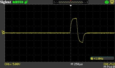
or Press:
- Minus button = for Negative then Positive:
18 volts peak to peak:
Frequency
When LCD is displaying:
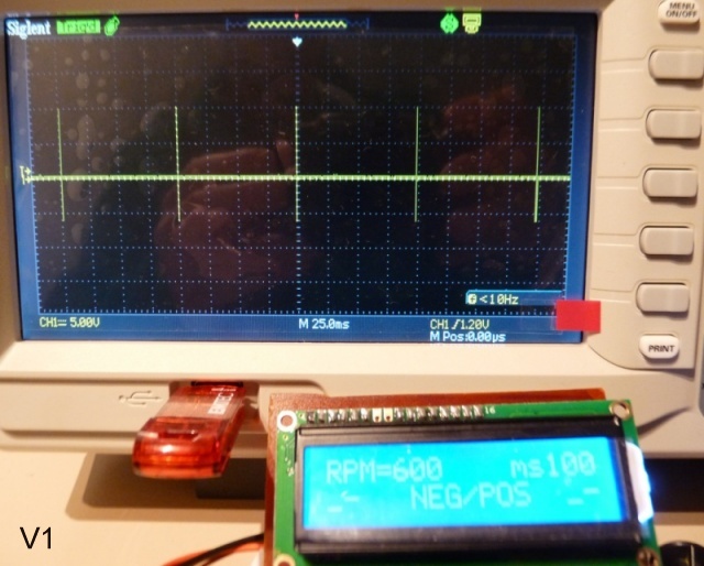
 +   RPM= 1000   -

NEG/POS
then Press:
- Plus button = increase RPM
- Minus button = decrease RPM
- Hold on the button to adjust faster
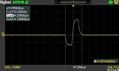
Perfect accuracy at 30000RPM = 500Hz = 2ms: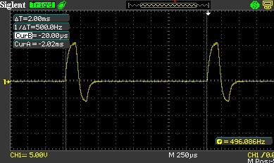
Additional features in version 3:
Sweep generator / Manual
When LCD is displaying:
Pickup adjust : ?

SWEEP or  MANUAL
then Press:
- Plus button (on the left) = AUTO mode
– The simulator will forever sweep the range 1000 to 30000RPM in 30 seconds.
– You can switch from SWEEP to MANUAL mode anytime by pressing a button. - Minus button (on the right) = MANUAL mode
– You can select RPM manually from 1000 to 30000RPM in a linear range 1000 by 1000rpm.
Memory
- When both buttons are pressed the same time, the actual RPM is saved in the memory and the simulator will start from this point when restarted.
 +   RPM= 6000   -

SAVED
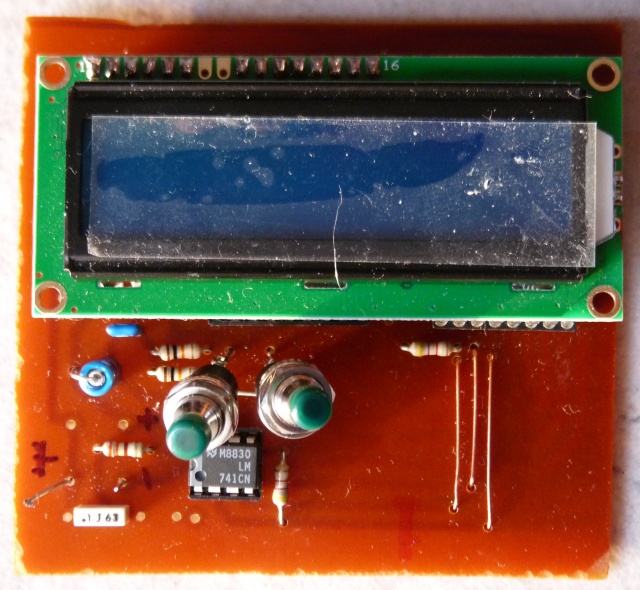
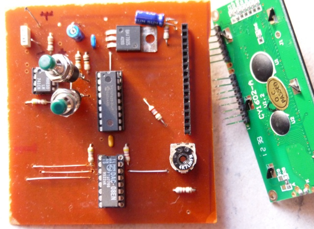
Pictures.
 |
 |
 |
 |
 |
 |
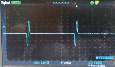
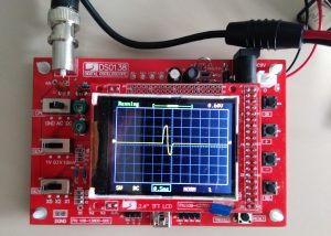
A check with a cheap DSO138 oscilloscope that I strongly suggest to buy if you are a bike mechanic.
Videos.
V3.0:
Video of a bench from 1000 to 30000RPM:
V3.2:
First use.
-
-
- Double check your PCB for no shorts or breaks.
- REMOVE the LCD display and ALL ICs from the board.
- Connect the 3 power wires: Ground | -9 to -15Vdc | +9 to +15Vdc.
The power voltage will determine what maximum output range it gives. - Check out the tension at the power pins of each IC support:
PIC: pins 14,5 DAC: 1,3,13,15 AOP: pins 7,4 and LCD support: pins 1,2,15. - Adjust R5 to get +10Vdc at pin14 of DAC08 which determine output current to have a full scale output.
The DAC can operate from -Vref to +Vref - Power off then ONLY insert PIC16F628.
- Connect a voltmeter to pin13 of the PIC. (or a 330ohm resistor + led)
- Power on the simulator.
- RB7 (pin13) goes high (+5v) for 1sec 2 times, then finally remain low meaning the programming is correct.
- Power off and insert the DAC0800, the AOP and the LCD display.
- If you don’t have a oscilloscope, you can connect a LED between the output and the ground.
- Power On. This Led will be off until you have selected the polarity (+/- or -/+) afterward the led slightly bright.
- A multimeter will still show 0 volt DC between output and gnd.
Only a oscilloscope can show you the pulses. - Enjoy!
-
Versionning.
-
-
- Version 1.0:
- Initial release. (235 to 4285rpm)
- with 16F628A Program memory:3.5Kb, RAM: 224b, EEPROM: 128b,
Ext clock: 20MHz, Internal clock:4MHz, 18pins
- Version 1.0:
-
- Version 2.0:
- [soft] 235 to 30 000RPM in a logarithm rise. (one step = 1millisecond)
- [hard] C5 moved on PCB
- Version 2.0:
-
- Version 2.2:
- [soft] Use pin13 as a programming checkup.
- Version 2.3:
- [soft] 300 to 30 000RPM in a logarithm scale.
- [soft] Bug corrected.
- Free software
- Version 2.2:
-
- Version 3.0:
- [soft] 1000 to 30 000RPM in 1000rpm steps.
- [soft] Starting RPM can be store in memory
- PIC to buy.
- Version 3.0:
-
- Version 3.1:
- [soft] Loop range (one step from 30.000 to 1000RPM and vice-versa)
- Version 3.1:
-
- Version 3.2:
- [soft] Sweep function to automaticaly browse the RPM range. (1000 by 1000)
- Version 3.2:
-
- Version 3.3:
- [soft] 1000 to 30.000RPM in 1000rpm steps.
- [soft] A push on any button stop the sweep mode.
- Version 3.3:
-
- Version 3.4:
- [soft] Range: 1000 to 20.000RPM in 500rpm steps.
- Version 3.4:
-
- Version 3.5:
- [soft] Range: 1000 to 12.500RPM in 250rpm steps.
- [hard] with 16F1847 Program memory:14Kb, RAM: 1024b, EEPROM: 256b,
Ext clock: 32MHz, Internal clock:32MHz, 18pins - PIC to buy.
- Version 3.5:
-
- Version 3.5c2:
- [hard] Add R3 to avoid DAC08 overheating
- Version 3.5c2:
-
Building a pickup simulator and in the setup it says one can use 9 to 15 volts (dual supply) so I use 2 x 9v batteries.
Now in the setup notes it also says “Adjust R5 to get +10Vdc at pin14 of DAC08”
How can I set this pin to 10v when I only have a maximum of 9?
I tried to clarify that above. The DAC can operate from -Vref to +Vref.
DAC0800 is a 8bit converter, meaning 256 steps. Each step size is Vref/256.
When the PIC output is 11111111, the output tension of the simulator is Vref then 10volts.
If Vref is only 8volts, then 11111111 will give +8V and 00000000 give -8v
It works, you just have a smaller range of voltage.
Hello.
I built a pickup simulator.
The image can not be attached, so the URL to the image is shown below.
? https://yahoo.jp/box/swYMrw
The software is freeware ver 2.2.
When I press the button and change the rotation speed, it is displayed on the LCD, but the output does not change why.
The pulse width of the output pin and the pulse width remain about 16 ms.
There is no problem with the polarity selection of the pickup, and it can be checked with the oscilloscope that the waveform also has the polarity selected.
I tried various investigations including mistakes in wiring, but I do not know what is wrong.
I used DAC is DAC0800 , not DAC08EN.
Is it not working properly unless it is DAC08EN?
Could you please give me some advice?
Thank you.
Hello,
It should work with both!
It’s curious that DAC always gives 16ms which is 3700RPM
The wave looks ok on your scope.
What you can do is :
– first: remove PIC & DAC and test the continuity of PCB between:
MSB LSB
DAC0800 5 6 7 8 9 10 11 12
16F628 9 8 7 6 13 12 11 10
MSB LSB
Also check other pins.
– second:
remove DAC
insert PIC
Focus on MSB (pin9 of PIC) with the scope looking if period is changing according to the LCD display.
– Have you check that MSB “blink” when you turn power on (it’s a test that prove programming is correct)
Th.
Hello,
Thank you for your reply.
I checked it again, but the problem was not found.
Subsequently, I probed the 9 pin of PIC and confirmed that a waveform will be generated after edge selection with the push switch.
The state of each pin immediately after turning on the power supply is as follows.
PIC 9 pin … Hi
PIC 6, 7, 8, 10, 11, 12, 13 … Lo
When an edge is selected in this state, a waveform appears.
As a pocket type logic analyzer will arrive today, I will use the analyzer to examine the signal between PIC and DAC.
I will contact you again.
Thank you.
> PIC 9 pin … Hi
pin9 is not supposed to stay HIGH, at least for 1second but on normal working it’s not a steady +5v !!
Set a 1000rpm you must measure 60ms between 2 pulses going out of pin9 (MSB) then change to say 4000RPM and you must read 15ms on your scope.
Th.
Hello,
Thank you for your reply.
I checked the waveform with a logic analyzer.
The software is PulseView.
The snapshot is uploaded to the following URL.
https://yahoo.jp/box/YEZQOK
Waveform timing does not change at 1000 RPM and 2000 RPM at all.
RB 3 (9 pin) of PIC is basically Hi level.
Wrong writing to PIC?
As a precaution we had programmed 2 PICs, but the same result.
PIC is PIC16F628A-I/P.
The program software is MPLAB IPE v 4.05.
I am pleased if you give me advice.
Thank you.
Thanks to your snapshot, I think I found a mistake in v2.2.HEX !
Try this v2.3.HEX, (cksum : 6766)
Koshi | 4 March 2018 at 2 h 38 min | Reply (Edit)
Hello,
Thank you for your reply.
I verified ver 2.3.
The interval between the waveform and the waveform has now changed, but there is still a problem.
Waveform generation timing is later than specification.
The faster it gets faster, the greater the deviation.
I uploaded an additional snapshot.
https://yahoo.jp/box/YEZQOK
At 1000 RPM (60mS), the waveform interval is 75mS which is 1.25 times.
At 2000 RPM (30mS), the waveform interval is 45mS which is 1.5 times.
At 20000 RPM (3mS), the waveform spacing is 18mS which is 6.0 times.
At 30000 RPM (2mS), the waveform spacing is 17mS which is 8.5 times.
Every time the rotation speed increases, it is getting late.
I think that there is a problem with loop processing in the program.
Would you please verify the program once more now.
Thank you.
Exact there was a problem during the loop!!
Please reload the new v2r3c1 on the web page which is much more accurate.
Thanks for this good feedback Koshi !
Hi Thierry, I have just built the simulator and when loading sim ver2r3c2 to the pick I get an error which says it is not recommended to program this device if both the internal oscillator and internal MCLR are selected. I am using MPLAB ICD2
Is this correct? I get no display at all and don’t know if it’s my lcd at fault or if it is a software problem. I am getting some pulses out of the unit but these don’t rise above 0 volts. (Suspect my Velleman pocket scope is on the blink!) I will check this with my bench scope tomorrow.
Best regards
Les
Hi Les
I don’t know MPLAB ICD2, it’s probably a WARNING, not a ERROR !
Have you compare the checksum and the word bytes?
Done all the steps I described in “First use” section?
Did you check RB7 at startup?
There are no output pulses until you have selected polarity edge.
if the LCD doesn’t work , you can wait 5seconds than press one button, wait 2seconds than press one button to select the polarity blindly…
Regards
Th.
Hi Theirry, thanks for the quick response. You’re right, it was just a warning. I tested oh pin 13 on the pic and got no pulses so I rewrote the software onto the chip and I also found that my lcd (not compatible and connected with 16 wires) was not working, found another lcd in my spares box that was pin to pin compatible but 4 rows.. Installes it and everything worked great! Many thanks for a really neat project.
Regards
Les
Hi Thierry, the simulator is working fine but the out put pulse is only 1.1 volts peak to peak, any ideas ?
Regards
Less
Hi, output connected or not? Tell everything pls.
Output on air, the range is the same as the range of the power supply.
If powered by +18Vdc and -18Vdc the output is around the same.
Th
Hi, only connected to scope, plus minus 12 v, dac adjusted to 10 v, pulsing ok 300 to 30000rpm, pulse selectable plus or minus, pos and neg 12v on both dac and op amp. Op amp is TL071 (texas equivalent of 741)
thanks
L
RTFM
If you don’t comply to the part list don’t ask for help.
🙁
Never use TL071 because of JFET input, use a regular 741 instead
I think the schematic is wrong.
I also had this problem; but with 3v pulse output and DAC0800 getting hotter than I’d expect.
Check DAC0800 datasheet – there should be Rref in series with Pin 14, equal to the RL = /RL, eg: R2 and R1. (Which are 4.7k)
I added a 4.7k resistor in series with Pin 14 from R5 wiper which increased the pulses to 8v and made the DAC0800 run much cooler.
I am not sure why I don’t get the full 10v, but perhaps there needs to be some more modifications.
I didn’t notice overheating but I used a 10k trimmer, that could explain…
You are right about the datasheet so I have corrected both SCH and PCB in version 3.5c2 available from now on.
Thanks for your feedback!
Th
Pingback: TESTER, ANALYZER – Transmic CDI
Hi ,
I am interested in reading the angle advance , i need to know how the negative voltage is generated to provide the negative reference to the DAC , and also it generatres a single pulse per RPM , can it generate double pulse ,in case of Toothed flywheel.
Hi,
It’s not generated, you have to provide positive and negative power supply. (ie 2 battery etc…)
This simulator is End Of Live. I will not modify it as it has been largely replaced by https://transmic.net/2019/08/12/cdi-tester-v4/
which generate ONE pos and ONE neg pulse.
Hi tierry
I am testing the entire circuit and when I test the Pic on pin 13 when putting it into operation 2.5v comes out and it stays with that fixed voltage and I do not know if I program it wrong.
I use PICKIT2 v2.60 and the configuration word that comes out is 2110 and Checksum 400D could be for this reason that it doesn’t program the PIC well
You have PCB to sell from version 2.3
Thank you
Hi Jose Luis,
The main question is : does the Simulator display the menu on the LCD display?
Because THIS IS the real test!
I don’t know what comes out of pin 13. Pin 13 is one of the 8bit data, sometime it’s +5v , sometime it’s 0v and it change quickly , you need a oscilloscope to read it.
Sorry they is no PCB. It’s EOL
Regards
Hi tierry
It seems that the LCD is bad because the letters come out in half and it has been solved.
But now I have another question how should I connect the oscilloscope because the output has a single cable and the mass of the oscilloscope where I connect it.
Thank you