
This ACCDI is EOL (end of live)
Characteristics.
- Easy to build.
- Advance curve slightly adjustable.
- Need a working charging coil for the capacitor.
- Don’t need a battery
- No rev-limiter
Limitations.
This CDI only does the ignition task, it doesn’t use any safety like neutral and sidestand.
- Connect directly Neutral switch wire to Neutral indicator.
- If you need “Side-stand security” then connect Sidestand switch to KILL wire of this CDI
DOWNLOAD
| AC-CDI Analog | v2.2 | |||
|---|---|---|---|---|
| To make the PCB | PCB.pdf | Parts list | ||
| To build the CDI | Schematic.pdf | components.jpg | ||
| To wire the CDI | Wiring | HowTo hock this CDI on Yamaha XT600 | ||
This circuit replace the genuine CDI.
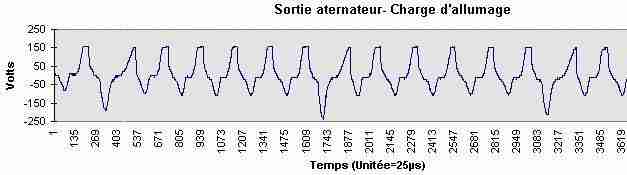
The charging coil produces a alternative voltage around 50Vac at idle to 200Vac at high RPM.
Output from Charging coil:
Tension at the SCR anode (at 1700rpm):
Both pickups gives AC pulses from ±10v (at idle) until ±20v (at WOT)
The 12° pickup (white/green) is used for idle and low RPM while 36° pickup (white/red) is used for high RPM.
(The green wire is the common of the both sensors)
At startup and idle, when the piston approaches the firing position, a positive pulse from the 12° pickup goes through D1-R2 then trigger the SCR T1.
T1 quickly discharge the energy stored in the capacitor C1 into the primary circuit of the ignition coil, where the voltage is stepped up in the secondary circuit to a high voltage sufficient to fire the spark plug.
At higher RPM, the positive pulses coming from 36° pickup goes through D2, R3, R2 and trigger the SCR.
There is a interesting video describing how a CDI works.
Sensitivity
This CDI doesn’t have seamless advance, it jump directly from 12° to 36° BTDC.
The moment where the CDI jump from Low advance (12°) to Full advance (36°) is adjustable by resistor R3
– The threshold is adjustable from 2000 to 5000rpm
Start tuning with R3 at the maximum value (totally screw) which is equivalent to 5000RPM then slowly unscrew it to lower the resistance, therefore the RPM where it switch.
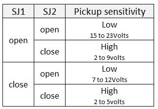
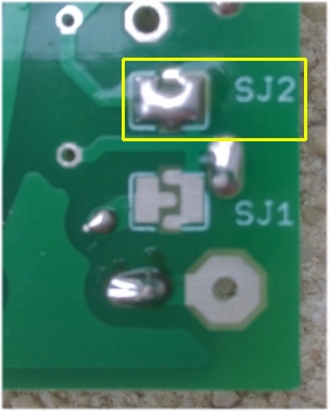
On the back side of the PCB, solder pad jumper SJ2 allow you to adjust the sensitivity according to your pickup coil connected on 36° input.
SJ1 slide those ranges lower.
| This ignition need either2 pickups: | or only one pickup |
1st pickup at 36° BTDC: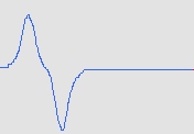 and 2nd pickup at 12° BTDC: 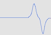 |
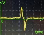
Positive then negative: |
But not negative then positive! |
If the pickup is not internally tied to ground inside the stator, you can reverse the polarity (NP to PN) by crossing the wires.
If the bike has only one pickup, connect it to the 36º input and leave the 12º input unconnected
Nota
It is not an error! With this short, we get this equivalent circuit:
D1 suppress the negative wave.
D2 allows the positive wave to pass.
D3 kills the negative peaks of tension
produced when the thyristor cuts off
Photos
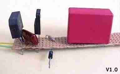
Version 1.0:
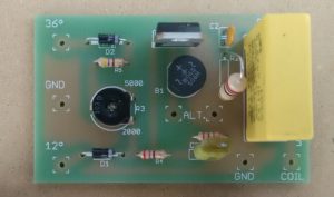
Version 2.1:
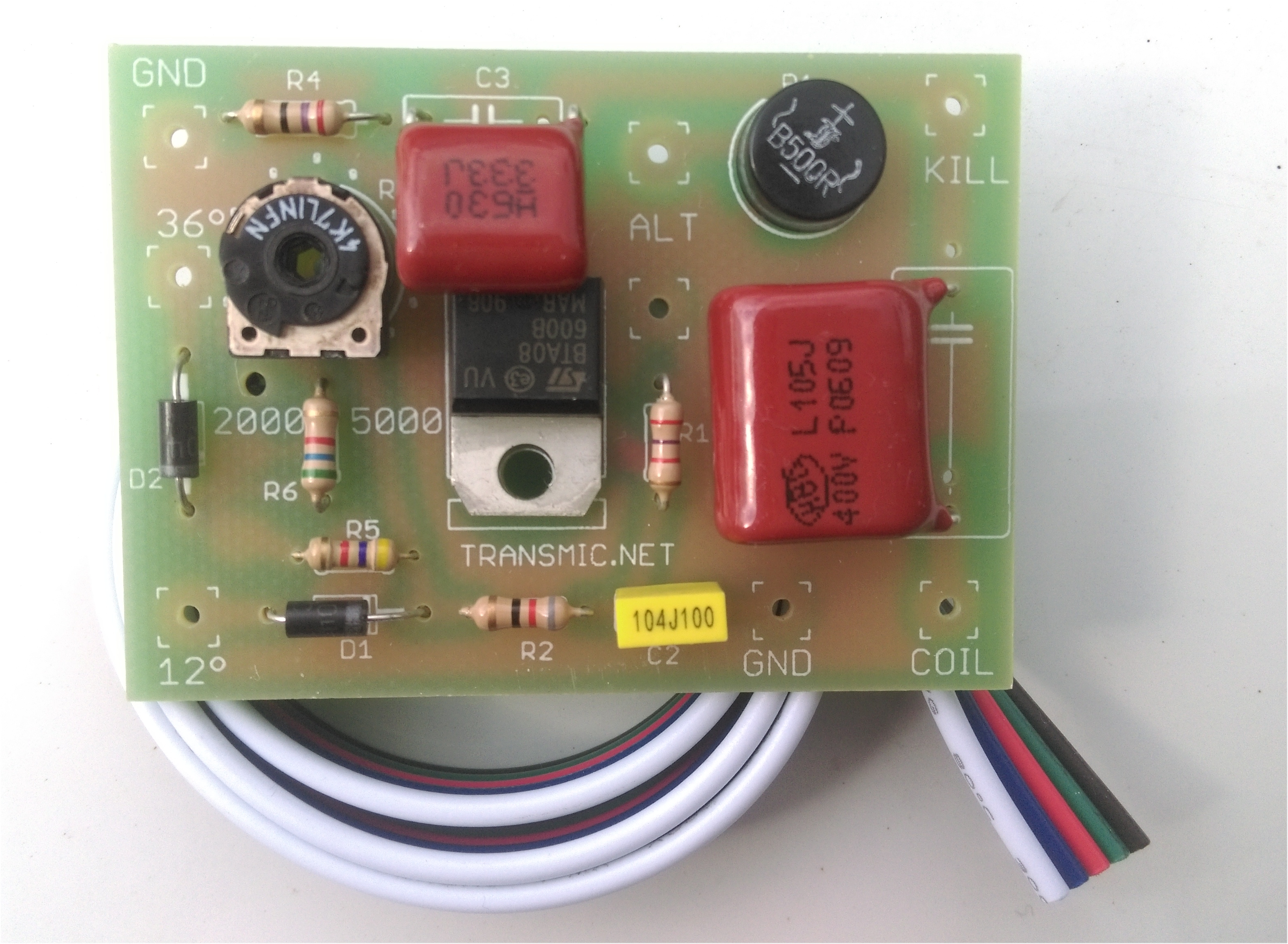
Version 2.2:
Videos
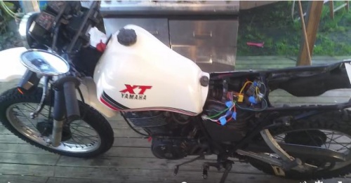
Analog CDI on a XT125/1982:
Analog CDI on a XT400:
Caveats
Never run the engine if the exit of the CDI is disconnected from the spark coil or if the ground is disconnected (PAD1 or PAD2 not connected) otherwise the tension rises over 1000volts and destroy the SCR.
Never run the engine without any spark plug: due to the high secondary voltage, it is possible to damage the internal insulation of the secondary coil.
This simple unit is design for XT, which have 2 pulsars: one for idle, one for middle/high rpm.
KLR and some others bikes have only one pickup for middle/high rpm range and there are some electronics inside their black box to delay the pulse at idle.
With this unit, the spark will appear too soon for the KLR. Therefore you’ll have kick back when kick start and (if it’s starts!), the engine will bang a lot at idle (this can damage the connecting rod)
I disclaim all responsibility !!
If it’s ok, well done! you made a success of your first electronic ignition.
You can use it to verify that your problem is a faulty CDI and as a spare unit.
 |
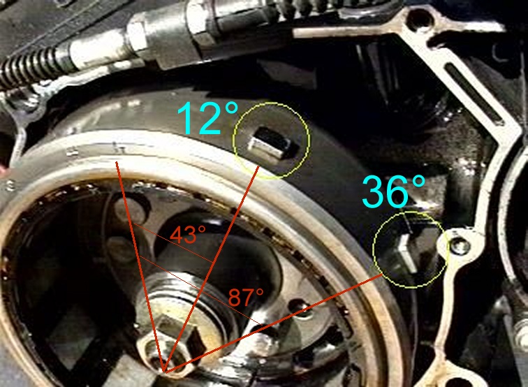  |
The pulse from second sensor (sensor A and magnet A on the left drawing) is early 12 ° before TDC.
(Reminder: the TDC is finds when the sign like a H engraved on the rotor is view by the small opening on the left crankcase.) The advance is sufficient to start the motor straight.
TROUBLESHOOTING
Step 1
See: troubleshoot step1
– Don’t connect the pickup(s)
– Don’t connect the Kill Switch
– Connect the ignition coil
– Remove the sparkplug from the engine and connect it to a GOOD metal frame (ground)
– Connect the charging coil
– Connect a voltmeter between Ground and Kill output
Then:
Kick start or electric start a few times.
The voltmeter should raise up to 100 or 200Vdc.
If not, check grounds, connections, charging coil (stator)
Step 2
See: troubleshoot step2
When the main capacitor is charged and the voltmeter shows 100 to 200Vdc
Then:
Connect the +12v plug from a battery to the 12deg input.
The capacitor discharge into the ignition coil and a spark must appear at the sparkplug.
If not check grounds, connections, SCR, spark plug cables
Step 3
See: troubleshoot step3
-Kick start or electric start a few times.
The voltmeter should raise up to 100 or 200Vdc.
Then:
-Connect the pickup coil to the 12deg input.
-Kick start or electric start once.
When the piston approaches the TDC and pass in front of the pickup, a positive pulse is send by the pickup and trigger the SCR.
The capacitor discharge into the ignition coil and a spark must appear at the sparkplug.
If not check grounds, connections, pickup coil, reverse the 2 wires of the pickup coil.
Step 4
See: troubleshoot step4
If you have checked that the pickup produce a voltage, a reason could be a too low voltage unable to trigger the SCR
Then:
-Short R2 resistor to increase the current that trigger the SCR.
-Try again step 3
ESTA INTERESANTE ME PODRIAS MANDAR EL DIAGRAMA ELECTRRICO.
TE LO AGRADESCO DE ANTEMANO ATENTAMENTE.FRAMK
Hello,
I’d be interrested to make on for my DR125, how do you connect it ? Some modifications to do ?
Schematics :
http://img11.hostingpics.net/pics/502880bobinage.jpg
Thanks !
Hi,
As you have only one pickup, connect it to GND and 36deg inputs.
You pointed the connector [P-Br] on the schematic but it could be the other connector on the right too: [Bl-G] I don’t know !
Check what wires goes to the pickup that look like that.
Bear in mind that polarity is of the most importance to get the positive pulse in the first place.
ie: connect GND to Bl and 36 to G
or connect GND to G and 36 to Bl.
A oscilloscope would be a BIG help to find what is what…
Wow, this design and information may be exactly what I need for a CDI replacement on my Suzuki GN400. The GN400 has two trigger pickups, one at 10 degree BTDC and the other at 35 degree BDTC. The trigger pickups have single wire from each and ground at the mount plate. I like the idea the transition from the 10 BTDC to the 35 BTDC pickup is automatic and adjustable for the RPM.
I have very good mechanical skills, I have done all my own work on my cycles for 35+ years. However, I have never built an electronic device. I do have a wiring schematic for my GN400 if that helps to determine how to best apply this CDI design.
As you described it, The Suzuki GN400 pickup wiring is exactly the same as Yamaha XT600 so the connection is straightforward.
Connect the 10deg hot wire output on the 12deg input. The 35 on the 36 deg input and connect the common ground.
But keep in mind that Suzuki pickups gives a NEGative pulse first !
As my CDI use the POSitive pulse, this one come later (less then 10deg BTDC, less then 35deg BTDC) the advance will be lower than with the genuine CDI.
Forgot to mention. I also have a CDI from a Suzuki SP500 that I thought may work as it is also an AC powered CDI with only one tripper pickup. However, it needs a trigger pickup with two wires, to ground at the CDI. The GN400 trigger pickup has only one wire, and it grounds at the pickup mount plate at the magneto. So I am not sure it would be adaptable to the ignition on the GN400.
The common wire can be grounded on pickup side or CDI side, that doesn’t matter.
The key point is : Is there the same number of pickup? (10 & 35deg BTDC)
i have a Hero honda cbz of 1999 model, which is 4 stroke single cylinder, 12 v ac (battery). the CDI is dead, No-where i am geting it. Please help me.
What type of ignition box is it?
TCI or DC-CDI or AC-CDI ?
if it’s AC-CDI try the analog one.
bonjour Thierry
sur la dernière image de cette page ou sont les 12 et 36 degrés?
quelque chose m echappe (60-47=13 capteur A???)(80-87???? capteurB)
cordialement, Yves
Bonjour Yves,
Je n’ai jamais résolu ce mystere non plus !
Comment 7° et 13° deviennent 12° et 36° ? Comme les capteurs analogiques reagissent avant que l’aimant soit pile en face, il y a forcement une difference de qq degres mais quand meme….
Cdt Th
Ok done. Will let you know how it goes in 36○ mode
https://www.facebook.com/justin.romaine/videos/10211410462191826/
Hi everyone.
Original CDI circuit. Analog ignition timing.
Yamaha YZ80-125 2T module dismantling result.
Link:http://www.elektroda.pl/rtvforum/viewtopic.php?p=16654881#16654881
Regards nyemi from hungary.
Hi !
Will this circuit works for honda cr125 1996?
Thank you !!!
Hello, I would try making this at home but the thing is, my low voltage AC supply for the lamps outputs 6VAC (5-9 actually) with 17W power output and the charging coil for the spark has direct contact from the black coil to the spark with breaker points for triggering.
I was thinking of putting ac-dc converter on the points for the 36° pickup which I can move with the plate holding the coils together to suit the timing but now the question is:
Do I connect the low voltage coil on the side where the 250VAC is on the schematics (alternator) and will it power up the PCB or is it too low power?
Hello,
I will not work.
A CDI need a high voltage to work: 100 to 200Vac. not less.
Is the coil connected to +12v on one side and to points on the other side?
Then it’s a TCI. Internal resistance of TCI coil doesn’t work with CDI boxes.
You would have to change the coil too…
Well there are 2 coils, one which makes high voltage for the spark (up to 8kV) going to spark on one side and through a capacitor on the points, so it discharges everytime the points break the circuit. There is another coil opposite which makes around 6VAC for the front and back lights. So not 2 charging coils but 1 and 1 for the lights.
I was thinking of converting 6VAC to DC and stepping it down to 5VDC and then making a PCB with low voltage chips to be similar to this one – a fixed slightly adjustible advance curve (maybe with two steps at 2 different RPMs; but not really needed since the motor i have already goes from 1.000RPM – 10.600RMP somewhat smoothly on 15° preset with points). I would like it to run on 6VAC, the original charging coil and the original breaker points because this way I wouldn’t need to switch it out.
But then comes the problem with lights, if it would take up much power I couldn’t have the lights on then.
You can e-mail me if you’d like to help me out and give me some tips. I know the basics of SMD PCB making and I have acces to alot of the materials and a dipping station so no problem making it, just to make the right one…
You don’t answer my question!
in Kettering ignition there are points and capacitor.
in high tension magneto there are points and capacitor.
Read this interesting page:
http://gpzweb.s3-website-us-east-1.amazonaws.com/Ignition/IgnitionTypesAndCoilWiring/IgnitionTypesAndCoilWiring.html
All I can say is micro-controller don’t draw a lot of current so using 6Vac rectified in 5Vdc will work without noticeable loss for the lamps.
Much more critical is
– how do you get 200Vac for charging a AC-CDI capacitor?
– how do you change the advance if you still use mechanical points? You must replace points by a IGBT transistor
I will not process to describe a magneto to AC-CDI conversion as it’s far beyond the subject of my web site and it’s not of a general interest IMO.
Good luck in your project.
Oh sorry for not replying, the motorbike is a small one with flyback magneto ignition and no battery.
So the flyback integrated magneto coil and ignition coil would have to be switched out for a stepped up magneto ignition (seperate charging and ignition coil) right?
Thanks for the tip on the page, got a wider view on the types of magnets and coils, very appreciated. Also thanks for the idea in the first place.
It’s still unclear what your goal is!
– install a AC-CDI ? => you don’t have any charging coil, the magneto coil cannot act as a charging coil.
– Replace points by transistor driven by a controller? => no matter if it’s flyback or stepped-up magneto !
You must keep the points to give the timing to a controller than the controller trigger a transistor that switch off the current in place of the points.
Bonjour Thierry,
Je possède un Yamaha 125 XT de 1986, similaire pour l’allumage au 125 XT de 1982 pour lequel vous avez fait un test positif avec votre boitier AC-CDI Analog.
Par contre, il ne me semble pas qu’il y ait 3 fils white/green, white/red et green venant du sensor mais seulement 2 fils green et white.
Dans ce cas, comment brancher ces 2 fils vert et blanc sur le CDI ? quelle couleur va sur ground et quelle couleur va sur 36° (car j’ai compris que lorsqu’on a “only one pickup” on utilise le 36° et pas le 12°) ?
Merci d’avance,
Thierry (également…)
Bonjour Thierry,
Effectivement selon les années, Yamaha a utilisé 1 ou 2 capteurs!
(La XT125/2007 par exemple n’a qu’un seul capteur a raccorder donc sur l’entrée 36°)
quelle couleur va sur ground?
Quelque soit le fil raccordé a GND, le pickup va fournir un signal MAIS la polarité va changer !
Ex: selon le fil connecté a GND, le pickup fournira une impulsion POSitive puis NEGative (OK):
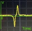
ou une impulsion NEGative puis POSitive (not OK):
Pour le voir, le mieux est un oscilloscope mais vous devriez y arriver avec un multimetre ANALOGIQUE en position millampéres.
En kickant, vous devriez trouver quel fil grounded permet de fournir POS /NEG sur l’autre fil.
Comme sur cette experience:
Bonjour,
Merci pour cette réponse. J’essaierai effectivement avec un multimètre analogique.
Sinon, je me dis qu’il suffit de tester directement sur la moto, en essayant les deux possibilités (en inversant les deux fils sur GND et 36). Il doit y avoir un cas où la moto démarre mieux ou fonctionne mieux ?
Sinon, autre question, je comprends que ce CDI est avec une avance à l’allumage fixe, quelque soit le régime moteur. Est-ce exact ? Cela a t-il un impact sur les performances du moteur et donc de la moto (couple, vitesse de pointe,…) ?
Merci d’avance,
Thierry
Did you ever sort out which wire is which? I have an xt200 with the same wiring and am pretty confident I have it right, but would be interested to know what you found out.
Hello, Ii Test it with a Yamaha TTR600 4T, at the moment it does not work, the original CDI is 12V powered by a regulator, should there be any problems?
I don test good signal of pikup.
Hi,
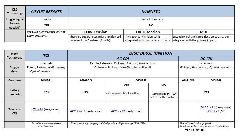
There are 2 different types of CDI :
AC-CDI powered by Alternating Current (~200Vac)
DC-CDI powered by Direct Current (+12Vdc)
ac-cdi cannot replace dc-cdi….. !!
OK, Thank you!
you do not have DC-CDi to sell?
Not yet.
bagaimana caranya memodif cdi ac dengan pilihan limit 6000rpm.9000rpm dan no limiter.kemudian kita bisa memilihnya dengan tombol manual.terima kasih
Hello thierry
How to modify or make rev limiter on your cdi design
It work for my yamaha 135cc 2 stroke..but i want rev limiter for my bike..!!
Thx thierry,,,and sorry for my english..
Hello Rahman,
Is it a Yamaha RX135 2strokes?
You cannot have a TRUE rev-limiter on those VERY simple analog CDI. (You need a digital one).
But you can try to increase C2 to 4.7uf or 10uf. It will lower the advance at 10000rpm and smother the engine.
Good luck.
Thankyou for your response. Yes is the same bike.
i try to make your CDI with little bit improvements value of components (i use cr3cm scr,1k on R1,and 2x470nf paralel on C1), and the results is really incredible
And surely i will try your advice.
I also made a digital CDI from you, version 7.9
But I don’t have enough data to draw the ignition curve.
So that my bike runs very badly. I think It needs trial and error , but I won’t give up before trying again.
🙂
Yamaha RX135 has a advance curve from 3deg at 1500 until 20deg at 5000RPM.
But you also have to use the right pickup position and the right polarity. A oscilloscope is useful the check that on the original CDI before the swap.
Good afternoon
I have a Kawasaki KLF 185 and the CDI box is the second weakest link in the 4 wheeler only behind the valve train.
The unit has one pulse pickup coil and from what I have read here I would hook up the pulsar (2wires) to the the 36 degree BTDC and ground the other wire. That being said how does this start with the spark being retarded so far? Or am I missing something in the design?
If this would work for my unit do you sell the entire kit or is this a build it yourself project and scrounge up the parts?
Any help is appreciate and thank you in advance.
Hi,
You read well and don’t miss anything. The magic comes from the VR (Variable Reluctance) pickup type.
On those ones, the voltage change with RPM and it’s where the advance is changing.
As I stressed, this simple CDI works best with a positive first pickup.
https://transmic.net/2016/07/24/analog/#comment-2721
Kawasaki is generaly a negative first sensor, meaning the positive wave is latter = bad timing.
The good thing for you is the pickup is separate so you can reverse the 2 wires hence the polarity.
Short answer:
it “should” work but may need to reverse the 2 wires for the pkp.
It is sold already built in the shop section here and on ebay. It’s a DIY thing, you have to sold the wires by yourself.
As you said the best way is to salvage the wires and connectors from the genuine broken unit.
(I’ll PM you soon.)
Th.
The TCI of my ’92 Yamaha XT600E 3TB is dead. What would be the best option to replace it? Could I use the Analog AC-CDI?
Take a paper and a pen than write 100 times:
TCI is Not CDI
TCI is Not CDI
…
lol
https://transmic.net/2016/07/02/faq/#tci
I plan to publish a TCI version this year.
How do I know if my pickup coil is low or high sensitivity? I have a 1982 Yamaha xt 125.
Thanks.
Hi,
XT125 has only one pickup so you have 2 choices:
– Try first to connect the pickup at the 36° input which is low sensitivity and adjustable.
if the bike is difficult to kickstart then:
– connect the pickup to the 12° input which is high sensitivity.
BR
Th
Hello,
I have a 1978 YZ400 with a suspected bad CDI, and looking into your layout/design. Do you feel this will work on the YZ400 2 stroke ?
It has 2 ac coils on the stator, a pickup of 3.4ohm and a advance coil of 174 ohm. I tried to test the ac voltage output on coils with it running and on the 3.4ohm coil I had 7v at idle and as I rev it went to 23v. The 174 ohm coil I couldn’t get accurate reading on as I feel it needs re-winding, I am in process of doing that now.
Thank you
Hi,
No it won’t! Yamaha YZ400 is a MAGNETO type ignition.
Hello thierry,
I have an rx 135 but it has only one pickup and 1 alternator, u have mentioned that if the bike has only 1 pickup then use 36°btdc but what to do with the alternator please help me out with this sir
Hi Prajwal,
The WIRING diagram in Download section here https://transmic.net/2016/07/24/analog/#download is pretty self-explanatory.
Thanks a lot sir for ur rply.. I think I should use the 200vac which is mentioned has red color wire which comes from the diode bridge
Thank you sir
Did you ever sort out which wire is which? I have an xt200 with the same wiring and am pretty confident I have it right, but would be interested to know what you found out.
You mean for every brands, every models, every years, every countries ? For sure not! 🙂
Only a close reading of the electrical schematic from your owner manual can give you the answer.
IE: XT200 should be Charging coil: R, Br. Pickup: G,W. Kill: Br/W. Ign coil: O
I am engineering student and I own an yamaha rx135 2stroke i saw ur cdi and I am interested in building that cdi but i have doubt the rx 135 has only one pickup and 1 alternator but in ur cdi u have mentioned 36°for one pickup but what about the alternator please help out with this sir please clear my doubt sir
Thank you sir
I have a XT600, 2KF It hasn’t been started in 10 years after a car crashed into me. I got it out of storage so I can get it going to sell and I had no spark. Nothing has been touched since the day of the crash when it last run.
Charge coil reads 50v-75v ac when kicking it over.
Both pickup coils have 120 ohm resistance.
Kill switch wire disconnected.
Neutral light illuminated, and when kicking the bike over there is no dc output at Orange wire to ignition coil.
Pickup coils measure about 0.3 volt when kicking over.
After reading your very informative page I have found that if I disconnect the pickup coil harness plug and kick it over a few times to charge the cdi, if I use an external 12 volt power source I can touch 12v + to the green/white pickup wire and I get a single spark. So it appears the cdi works, but the pickup coil voltage is not strong enough to trigger the scr in the cdi, is this correct?
Can I ask what sort of voltage the pickup coil should be generating when kicking over to trigger the scr to activate? And what is the minimum voltage the scr needs to activate? Do you think my pickup coils are faulty even though the resistance is within spec?
Any suggestions would be greatly appreciated.
First off you cannot measure the dc output at orange wire. No multimeter are able to see a 1millisecond pulse only a scope do.
Some thing for the pickup, use a classical voltmeter instead (with needle) . A digital one show the mean of the value and a pickup push out 5v max at idle but 1% of the time.
(1% of 5v could be a mean of 0,3v)
All in all pickups, charging coil seems OK,
>So it appears the cdi works
Correct! But a bad harness or a rusty gnd connection can raise the resistance to a point where the pickup voltage wont be enough to trigger the SCR. I’d check that first.
Hey,
just installed the AC-CDI ANALOG v2.2 on a XT 550 (1982) and i dont know how to configure the R3 resistor. To you know how much resistant is right for the 36° pickup or a method to check it?
hi, I cannot tell as it depend on how much voltage gives the 36° pickup AND how much sensitive is the SCR. That’s why it’s adjustable!
Start from R3 at max then lower it. If the input doesn’t work with R3 at min, look for a cut in tracks, bad joint then ask yourself if the pickup is really working!? I had a faulty one myself…
No method, ONLY a scope can show.
The bike runs okay. I just don’t know if it could run better. It’s just hard to figure out when you don’t have a scope. So I will try and error till i’am okay with the result then?
Yes it’s the only solution then!
Why not build a simple sound card scope that cost nothing??
https://transmic.net/scope/interface_soundcard.pdf
Hi Thierry
On the yamaha twin cylinders 2 strokes (RD, TZR, TDR) there is one pickup coil but two load coils, in that case how to connect these coils in your CDI ?
regards
Hi,
I supposed the crankshaft angle is 180° as they is only one jumbo spark coil to fire both cyl at the same time?
I think there is a central tap on the ignition coil. Takes some electrical measures to verify and use the 2 extreme taps of the coil to get the maximum voltage.
One end will be connected to ground while the other feed the ACCDI.
Also I strongly suggest to move to AC-CDI v2.4
Th
Hi,
You’re right, there is a central tap on the load coil, resistance from extreme 1 to central is 5 ohms, central to extreme 2 is 220 ohms and extreme 1 to extreme 2 is 225 ohms.
The crankshaft angle is 180° and there is one ignition coil with two spark plugs, there are two magnets on the flywheel (opposed 180°) so two ignitions per revolution with wasted sparks, at 12000 rpm we have 24000 ignitions (400 Hz), can the AC-CDI v2.4 handle it ?
What about the AC-CDI V9 ?
Regards
Yes it will. Analog CDIs are pure simplicity: one pickup = one spark no matter what!
Whereas AC-CDI v9 is limited to 20Krpm , so 10K on your engine, but the adjustable range is limited to 10k = 5000rpm with this 2 strokes engine!
In summary from 5000 to 12000 there is no way to adjust the timing.
Hi sir, I have made ur cdi for my rx135 ported its working great for normal rx135 but for kine which is ported I am not getting the initial torque so what can I do to get the torque
Hi,
This analog CDI is simple and there is not much you can do!
You can try to add a 1uf or 4.7uf in parallel with trimmer R3…
To get the most of a improved engine, you need a digital CDI (with processor) to adjust the timing at some RPM according to the mods/port you have done.
Thank you sir for the reply, I didn’t understand the what is the use of c4 33n 200vac , and is it necessary to use it in source coil
Hi, C6 and R3 are a snubber. https://en.wikipedia.org/wiki/Snubber