
End Of Live
EOL also mean: NO SUPPORT
You make it at your own risk.CHARACTERISTICS.
- Adaptable to other single-cylinder bikes.
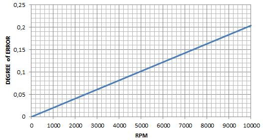
- Accuracy (0.15°/8000RPM).
- Advance curve is in EEPROM and can be freely modified
- 100 to 30.000 RPM
- Optional rev-limiter
- Need a working charging coil for the capacitor.
- Need a 6 or 12v battery
- Firmware for PIC16F1827 16MHz (or PIC16F628A 4MHz)
- PCB can use both 16F1827 or 16F628A
- Source code NOT available
DOWNLOAD
| PIC 16F628A / 16F1827 | files | |
|---|---|---|
| Make the PCB for 16F628A or 16F1827: | PCB Layout | |
| or Buy the PCB for 16F628A or 16F1827: | SHOP | |
| Build the CDI: | Schematic | |
| BOM/Partlist | ||
| Draw the advance timing curve for 16F1827: | Excel file for 16F1827 | |
| Draw the advance timing curve for 16F628A: | Excel file for 16F628A | |
| Burn the PIC 16F628A or 16F1827: | End Of Live | |
(Source code is not available.)
Free and Full Firmware are in the SHOP section.
Add the free firmware to your basket then go to pay ZERO euro.
Click on “View basket” or on the “basket icon” on the upper-right > Click on “Checkout” > Fill in the “Billing form” > you are not charged, it’s FREE >Click “Place order” > You will receive immediately a link to download the firmware and a email with this link.
WHAT DO YOU NEED?
HOW DOES IT WORK?

In the following I describe how this CDI works on a XT600 which have 2 pickup at 12° and 36°BTDC but it works too with others values or with only one pickup.
If the bike has only one pickup, connect it to the 36° input and leave the 12° input unconnected.
In case of 2 pickup, the SCR receives the pulse from the 12° pickup to directly trigger the SCR via D8 R7 C9.
The PIC only receives the pulses from the 36° pickup.
Of course the PIC cannot jump in time to ADVANCE the spark, it can only DELAY it.
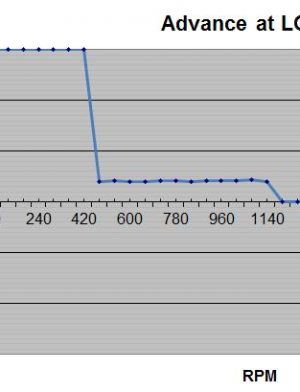
That’s why the pickup signal used is set at the maximum advance (Here: 36 deg. before TDC for an XT600)
At idle and low RPM, the PIC generates maximum delay (about 36° if programmed for an XT600) before fire a spark a few degrees ahead of TDC.
The spark fired by the PIC comes a few degrees AFTER the spark triggered directly by the SCR at 12° BTDC (for an XT600).
So that the 12° pickup is the one to fire the engine and the PIC triggered spark does nothing since it comes a few degrees later.
That way, there is no or little advance from TDC at low RPM.
As the RPM increases, the more the advance would increase ahead of TDC accordingly. (Delay is inversely proportional to engine speed.)
At a point where the timing curve passes 12° the PIC takes over from the 12° pickup and because it fires sooner, it is the one to fire the engine so when the 12° pickup triggers the SCR it does nothing.
As the PIC takes over it follows the ignition timing curve programmed in EEPROM.
Thus the more the speed increases the more the delay is reduced, advancing the spark. At high speed there is no delay, thus give the maximum 36 degree advance.
Pickup signal must be > 2 volts in order to be detected by the PIC
A 0.5ms pulse, delayed according to the Eeprom values (the timing curve), is available at pin 1 and trigger the SCR T1 via D4,R7,C9.
This pulse is manually adjustable from 0.5ms until 5ms or can adjust itself automatically: (from 5ms at idle shorten to 0.5ms at max rev.)
HOW TO PROGRAM THE CDI?
See: CDI programming with PicKit3 Software
2 or 4 strokes, 1 or 2 cylinders…?
See: CDI compatibility
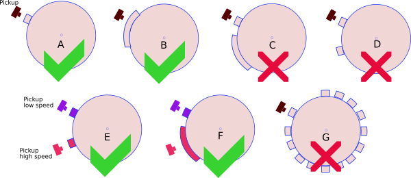
PICKUP
A pickup (aka: VR, Variable Reluctor, Reluctor) is a sensor that have a signal wires and a ground wire.
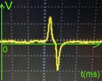
It’s made of a coil of wire wrapped around a magnet. When a ferrous part passes by the magnet, the magnetic field is modified and a voltage pulse is created in the coil generating a sine wave.
– 1 input for inductive pickup with 1 signal per crank rev.
– Pickup must puts out 3 to 30Vac
– Points, reluctors, Hall sensor, optical sensors can be used as long as they give only 1 pulse per revolution.
– This CDI works with 1 pickup and 1 reluctor (the metal strip on the flywheel) [A,B].
– This CDI works with 2 pickup and 2 bars [E,F].
– This CDI DOES NOT work with 1 pickup and multi-pulses pickup (ie 2 reluctors on flywheel) [C,D].
– This CDI DOES NOT work with 1 pickup and missing tooth flywheel [G].
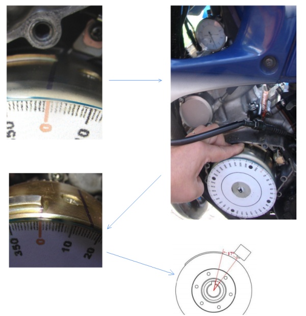
How to calculate the Pickup Position?
- Find the TDC
- Read comment here and here
Pickup Polarity
Check the polarity of the pickup (NP: Negative then Positive or the opposite PN) with a Needle galvanometer (in milliAmp position) while kicking or better: Use your laptop as an oscilloscope with this cheap interface. 😉
For a better understanding, this video can help.
Compatibility with others pickups.
CDI v7 can be triggered either by a positive-first pickup signal or a negative-first signal.
My cdi ONLY detect the positive going edge of the trigger pulse, if the positive wave is the second one like Honda or Suzuki, the timing will be bad…
In one word: The FIRST wave MUST be POSITIVE.
If your pickup gives out a NEGATIVE first pulse, there are 2 workarounds:
1) Invert the 2 wires that come from the pickup to the CDI if none of them are internally connected to GND
2) OR use Q1 and Q2 transistors to reverse the first negative signal so it becomes positive.
According to YOUR pickup signal, just use and sold the appropriate components:
For positive-first pickup signal (PN) |
|
Yamaha, Kawasaki |
|
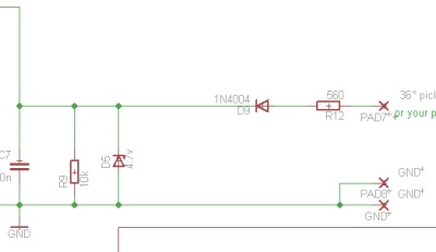 |
 Remove: Q1, Q2, R10, R11. Add : D5, D9, R9. |
For negative-first pickup signal (NP) |
|
Honda, Suzuki |
|
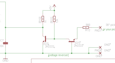 |
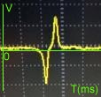 Remove: D5, D9, R9. Add : Q1, Q2, R10, R11. 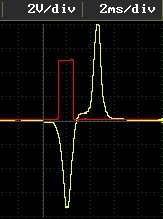 Yellow: pickup signal Red: PIC input |
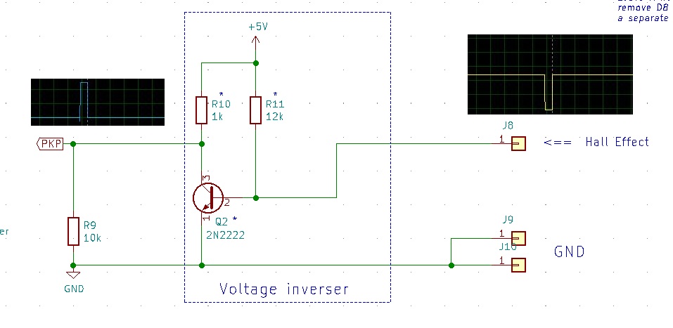
HALL EFFECT SENSOR
Most often, Hall sensor output are default HIGH, going LOW when a magnet pass in front of them.
To use an Hall sensor with ACCDIv79 or DCCDIv79 we need to invert the signal with one NPN transistor:
Simulation
Precision
- Error in degree of advance:
Tachometer
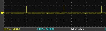
[TP1]: A tachometer output is available at pin11.
The tacho output is a +5v level and 5% Duty Cycle signal.
For tachometers that need a +12v level at 50% DC signal an external processor IC3 is available here:
Duty Cycle Converter
(Needs Q3 + R13 + R14)
LEDs
– At startup, Led D3 flashes 3 or 4 times and goes OFF meaning that programming was correct.
(if it doesn’t flash, something went wrong with the PIC or the power line or the programming…)
Led flash can be removed by seting “Led diagnostic” to No in XLS file.
– FreeTrial After 50 startups there is no more trial left and LED blinks continually. CDI won’t start.
– When PIC input pin10 is high [must be >2.4v], led D3 (pin2) brights.
So at each input pulse received from the pickup, LED D3 blinks in phase.
– If LED D3 always brights, that mean pin10 is always high! => Measure pin10 and try to lower R9 value from 10Kohm to 1.8Kohm or less according to your pickup.
– At each pulse LED D3 blinks.
(Blinking is very short: 0.0005 second, so you can hardly see ONE pulse, but when there are a lot of pulses, you can see the led glowing)
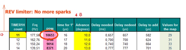
RPM limitation:
The firmware doesn’t contain any limit, for that matter a video below show it working at 30’000RPM !
There are 2 ways of limiting the RPM:
First in the Excel file: Above the highest RPM value in the sheet, there is no more sparks.
ie: when RPM goes over 10653, sparks stops.
Second: With JP2 jumper.
Jumper
JP2: REV LIMITER
If jumper is ON (meaning putting a jumper, so RA1/pin18 is connected to ground) then Optional RPM limit is activated. [cell N34 of Advance_curve tab].
If jumper is OFF (no jumper, so RA1/pin18 is connected to +5v through R5) then RPM limit is cell D9 of Advance_curve tab.
This jumper can be use as a racing/legal switch.
(Even if JP2 is not used, R5 is mandatory!)
Troubleshooting
– You can check the cdi the same way as V6
Reset diagnostic
After a reset:
– If led blinks 3 times it means that +5v has been cut (CDI has been powered off.)
– If led blinks 4 times it means that a RESET occurred (Manual or due to parasitic transient/aka EMI)
EMI
Electromagnetic Interference comes when external high dV/dT append nearby the processor.
– Only use ignition coil designed for CDI (not for TCI!)
– Use 5K to 20Kohm spark cap noise eliminator
– Use shielded sparkplug wire
– Ground shift: Sparks induce high current in the ground line. If gnd trace or wire are too narrow, ground level will raise up. Use a separate strong ground wire as close as SCR’s cathode as possible. Don’t use a unique ground path for microcontroller AND ignition coil!
– Add a filter across the SCR (snubber, varistor, Ferrite bead choke)
– Search for bad solder joint
– Use a good power rail strong and stable, can need more caps on it. (100uf + 100nf + 10nf)
– Add 100nF decoupling cap to power supply pins as close to the PIC as possible
– Add 100nF between reset pin (MCLR pin4) to ground
– Lower R1 pullup resistor to 4.7k
– No floating pins. Ground any unused pins if they are at low state.
– Use the last firmware
– Shield the circuit: Enclose the PCB inside a metallic box connected to ground.
How To simulate a VR pickup.
Upgrade the firmware
To upgrade the firmware without losing the timing data in the Eeprom, pls follow this order:
Connect PICkit3 to the PC
Launch PICkit3 Software, goto:
Tools > Check communication
Device Family > Midrange > 1.8v Min
Device: Select Part 16F1827
Uncheck “EEPROM Data”
Check “Program Memory”
File > Import HEX
Load the new firmware > Write
VIDEOS.
- After Firmware tuning and a 1000km proof test without any issue. (Thanks to “Toe T.”):
- Video of v7.9 on a Gilera 125cc model 1980:
- Video of v7.9r10 on a Suzuki DR800:
- Video of v7.9 on a Bench from 1000 to 13000RPM:
- See wasted spark and advance in real time:
- How a pickup works?
- Video of a bench from 1000 to 30000RPM with the pickup simulator:
- Led blinking when powering on. (v7.8)
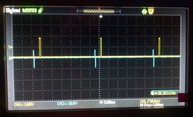
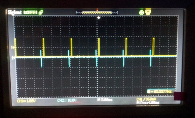
- Firmware V7.9R7 at 2000 RPM
( Blue trace below = input pin 10 = pickup signal and Yellow trace at the top = output pin 1)
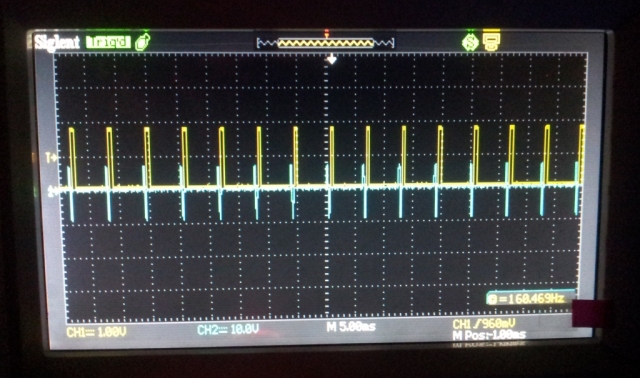
- Firmware V7.9R7 at 4000 RPM
- Firmware V7.9R7 at 10000 RPM
BOX.
You may have a look for a box of 76x53x20 millimeters dimensions.
ie: Hammond 1550P IP54 Diecast Aluminium Enclosure (80 x 55 x 25mm)
Thanks to Sylvain B. who print this 3D box and share the STL files.
VERSIONS
- Version 7.0:
- First Version.
- Version 7.1:
- [soft] Advance at low RPM adjustable.
- Version 7.2:
- [soft] Bug fixes
- [soft] Suppress adjustment at low RPM.
- Version 7.3:
- [soft] Bug fix. Adjustment at low RPM available.
- Version 7.4:
- [soft] Self generation of sparks.
- [hard] Reorientation of D3,C10.
- Version 7.5:
- [soft] pull-up resistors active.
- [soft] unused pins configured as output. (ECM protection).
- [hard] C1 = 10nF (ECM protection).
- [hard] JP1 move to portB (for pullup res.).
- [hard] add JP2 (for future use).
- Version 7.6:
- [soft] Internal pull-up resistors disabled.
- [soft] Led D3 goes off immediately when pickup switch to low state.
- [soft] PIC fuse: Power Up Timer: enabled.
- [soft] PIC fuse: Brown Out Detect: disabled.
- [soft] PIC fuse: Master Clear Enable: enabled.
- [soft] PIC fuse: Watchdog: disabled.
- [hard] JP1 move to RB2, [JP2] move to RA1.
- [hard] Add 2 external pull-up resistors R5+R12.
- Version 7.7:
- [soft] Bug fixes.
- [soft] Suppress adjustment at low RPM.
- Version 7.8:
- [soft] accuracy increased. (1.5° at 8000rpm)
- Version 7.9R7:
- [soft] Adjustment at low RPM available. (<1000rpm)
- [soft] LED D3 blink 2 times on startup.
- [soft] LED D3 is off in auto-spark mode.
- [soft] Usage of a 16bits Timer.
- [soft] PIC fuse: Watchdog ON to restart the microprocessor if crashed.
- [soft] No more checksum errors when loading Intel8HEX file in ICPROG.
- [soft] Output pulse that trigger the SCR is shorter (500µs) to reach higher RPM.
- [hard] Add D1 for ICSP connector.
- [hard] C6 goes 1500uF/16v.
- Version 7.9R8:
- [soft] TP1 goes from pin 7 to pin 11
- [hard] TP1 goes from pin 7 to pin 11
- [hard] All unused pins are grounded
- [hard] R1 increased to 10K
- Version 7.9R9:
- [hard.] R9 goes from 470K to 10K
- [soft.] Correction in Excel file about 2 and 4 strokes
- Version 7.9R10:
- [soft.] Improvement for low rpm adjustment in Excel file
- Version 7.9R11:
- [soft.] Major correction (prescaler value wasn’t transmitted)
- Version 7.9R11c1:
- [soft.] Change the display at low RPM in the Excel file.
- Version 7.9R11c2:
- [soft.] Larger adjustable range at low RPM
- Version 7.9R11c3:
- [soft.] Change the display at low RPM in the Excel file.
- Version 7.9R12c0:
- [soft.] Add RPM limiter. Can handle pickup position upper then 50deg.
- Version 7.9R13c0:
- [soft.] Add SCR trigger pulse adjustable from 0.5ms until 5ms.
- Version 7.9R13c1:
- [soft.] Fix Excel sheet.
- Version 7.9R13c2:
- [soft.] Define RA1 as input.
- Version 7.9R14c0:
- [soft.] Auto adjustable pulse width to SCR. Code Protection ON
- Version 7.9R14c1:
- [soft.] Code Protection OFF.
- Version 7.9R15c0:
- [soft.] Define RB3 as Output.
- [soft.] JP2 is used to BYPASS the advance curve. WARNING: USE IT ON A BENCH FOR TEST ONLY !
- [xls.] Major correction in “Advance at low RPM” tab. (Advance value displayed was relative, not absolute.)
- [hard.] Suppress unused TP2 output.
- [hard.] R7 lower from 330 to 180 to drive BTA type SCR.
- [hard.] Suppress C9-100n that could destroy PIC output in same cases.
- [hard] Drilling of Pads goes from 1.4 to 1.6mm.
- Version 7.9R16c0:
- [xls.] Correction in “Advance at low RPM” tab.
- [soft.] Major improvement of precision.
- Version 7.9R16c1:
- [xls.] Enhance accuracy in “Advance at low RPM” tab.
- [soft.] Enhance accuracy when use of 40us steps.
- Version 7.9R17c0:
- [soft.] Now firmware is a paid product downloadable in Shop Section.
- [soft.] JP2 used to activate a Rev-Limiter.
- [xls.] Add a optional Rev-Limiter.
- Version 7.9R18c0:
- [soft+xls.] Change calculation below 500 RPM.
- Version 7.9R19c0:
- [soft+xls.] Major improvement at low RPM.
CDI is now working from 2Hz/120rpm (Meaning easier kickstart, steady idle). - [soft+xls.] Allow pickup positioning as far as 360° btdc.
- [soft+xls.] Major improvement at low RPM.
- Version 7.9R20c0:
- [soft.] Increase accuracy
- [soft.] Add a PIC reset if power goes below 4v
- [soft.] JP2 Rev-Limiter is usable on the go.
- [soft.] Remove oscillator output. Remove JP1 (autospark)
- [soft.] Fix error at Rev Limiter
- [soft.] Fix bug at 450rpm
- [soft.] Fix led that doesn’t go off at RevLimit
- [hard.] PCB has room for the second PIC option for tachometer
- Version 7.9R20c1:
- [soft.] Unused RB2 pin set as output
- Version 7.9R20c2:
- [soft.] Disable PIC reset if power goes below 4v (BOR)
- [soft.] EOL. This is the FINAL VERSION FOR 16F628A. No more improvement.
- Version 7.9R21c0:
- [soft.] Firmware carried to a 4 time faster PIC 16F1827
- [soft.] Usage of INTERRUPT to largely improve accuracy, especially at LOW RPM
- [soft.] Detection of pickup when it goes low.
- Version 7.9R21c4:
- [soft.] Major correction of advance timing at low RPM
- [soft.] Many improvements
- [soft.] Add Debug diagnosis with LED
- [soft.] LED blinking at startup can be disable to speed up the start
- [soft.] Better detection of slow pickup signal
- [soft.] Better protection against EMI
- [soft.] Free version goes from 20 to 50 trials without led blinking.
- Version 7.9R22c0:
- [soft.] Now 160 RPM values are adjustable (+66%)
- [soft.] Lowest RPM is now 100 RPM
- [soft.] First measurement of RPM can be disable to speed up the start
- [soft.] Add an operational hysteresis to filter noisy VR pickup
- [soft.] LED blinks forever when trial version is expired
- [soft.] EMI protection improved
- Version 7.9R23c0:
- [soft.] Use different step value for low and high RPM to avoid too many XLS warnings
- Version 7.9R23c1:
- [soft.] Correction: RPM now changes when 4stk is selected
- Version 7.9R24c0:
- [soft+xls.] Simplification of LOW RPM settings.
- [soft.] Advance timing is now perfectly flat from 100 to 1000RPM.
I made the version cdi ac-cdi-16F628-v7-9 and it worked very well. CDI_16F628_V7.9R8.hex you load the program and run. It has a fixed 14 degree curve. Now my bike adecuare the curve that best walk as it is a reform of an old bike model Gilera 215 1980 Made in Argentina (Based on engine Gilera 98 Giubileo Italian)
Excel file has been corrected because of a error while setting to 4 strokes which didn’t change the values. Now it’s fixed.
Thanks to Cristian to spot it.
THANK YOU great site Built one extremely happy.Going to try a dual setup on the 4 cylinder drag bike when i have time available and see if i can build optical sensors for it
THANKS AGAIN
Fantastic !
using this CDI for a 4cyl is easy if the engine has a mechanical distributor (Delco) but much more challenging if using 4 electronic driven coils….
The idea is to use 2 Huandai dual cdi ht coils 2 programmable units ie one for cylinders 1-4 the other for no s 2-3,optic sensors for a bit more precision wish me luck as we breathe life into a 35 year old monster again
Hi , my derbi atlantis 50cc 2000 not have captor coil , how to install cdi programable in the bike ?
You can’t! My CDI needs a pickup.
Your CDI is certainly using the alternator AC voltage to trigger the SCR.
You would try to use those kind of CDI without pickup:
https://fotki.yandex.ru/next/users/kvadrat67/album/34133/view/234984
or
https://fotki.yandex.ru/next/users/kvadrat67/album/34133/view/205480
hola, te escribo desde argentina, quiero esamblar el cdi, pero tengo dos dudas, con respecto al pickup como puedo saber que tipo de señal obtengo, si positva o negativa y la otra pregunta es cuando te referis a la posicion fisica del pick up, seria cuanto grados esta desplazado del punto muerto superior del paso del sensor.
te comento que lo pienso probar en un motor chino 150cc copia de un motor honda. espero tu respuesta y si puedo contartacme contigo por otro medio para consultarte. gracias
Hello, I write from Argentina, I want esamblar the cdi, but I have two questions, regarding the pickup as I can know what kind of signal get, if positva or negative and the other question is when do you mean the physical position of the pick up, as would be degree it is shifted TDC sensor passage.
I mention that I think try at a Chinese copy of a 150cc engine Honda engine. I hope your answer and if I can contartacme you by other means to consult you. Thank you
Hello,
I can’t think of anything else then using a oscilloscope or a cheaper PC sound card scope to see if the pickup signal is positive then negative or the other way.
By position of the pickup, I mean the “electrical position” not the “mechanical position“.
In other words, you’re right: How much degree between pickup and TDC?
Generally it’s between 20 to 40 BTDC
friend I hope this good, I am writing from Colombia visit their website and found it very interesting because I like to know that CDI competition can build to put my bike competition is a yamaha bike rx 115. THANK YOU for your attention, I hope his answer soon
@Angel: The same old question…
2 strokes, 4strokes, 1-2-3-4-6 cylinders, mechanical/electronic distribution
separate pickup or not, analog or digital pickup, TCI, AC-CDI, DC-CDI etc etc…
There are so many different bikes that I can’t answer this!!
If I try to summarize:
Multi-cylinders:
If the sparks distribution is mechanical with the use of an old Delco distributor
=>my CDI works (BUT 2000rpm in the XLS file for 1cyl equal 1000rpm for 4cyl.)
If there are multiple coils (ie: 4 coils for 4 spark plugs) the CDI should be able to drive each coil independently but it cannot! It’s just able to drive only one coil.
=>my CDI wont work
Bi-cylinders:
my CDI works on BMW as they are opposed twin/4 strokes, and needs only one spark every 360°, the very same as a single cylinder/2 strokes.
HT coil is double, so it generates at the same time 2 sparks, and one is wasted as the other cylinder is on its exhaust stroke.
=>my CDI should work
For Bi that are not opposed, => my CDI wont work
Single-cylinder:
If there is no pickup and the timing is done by using the High Voltage of the alternator
=>my CDI wont work
If there is a pickup providing at least +3 volts
=>my CDI should work
but you eventually have to reverse the signal to get a positive signal first in order to have a good timing.
Friend Thanks for your reply. My bike is a 2-stroke has a loading coil and other pulsora. and each has a cable and my bike is competitive CDI recommends me
Hi Thierry
A ‘like very much thumbs up’ and order placed . A question on 2 stroke singles . Tach drive normally taken from coil LT wire from standard CDI .Is the pulse reaching the primary winding of the coil the same or does it require modifying ? Exhaust valve YPVS or Honda RC type that require a signal from the CDI unit to drive the exhaust valve controller ECU .Probably rpm pulse but from which point is this taken ? Should I check the output of the original CDI to the EV ecu and measure +V and then take use a similar source from your replacement CDI ?
General questions .Do you have a recommended Hamilton case for your pcb’s ?Is it worth swapping out the 2n2222’s for the more heavy duty XT450s in this minor application for reliability’s sake ?
Do you have plans for a combined programmable EFI/CDI for singles and 2 strokes .I hqve used mechanical fuel injection in the past on 2 strokes with lack of real success ,and used Tillotson types with great success, and flat slide carbs are great but the whole idea of dispensing with the mechanical issues and bucket loads of jets needles etc.these have with them appeals to me now that there are piles of motorcycle sized components about to adapt to 2 and 4 stroke single applications.Mikuni throttle bodies that will slip straight into a carburettor manifolds of various sizes complete with sensors for very little money.
Keep up the good work .
Thanks Malcolm !
As far as I know YPVS valve driving signal is a saw tooth form going from 0 to around 50volts
A few guys have taken the signal from SCR anode with success.
If I were you I’d have a look at the original signal if/when it work to see how it looks like then use the anode signal and lower it with a zener diode if needed. I can’t imagine that the aspect of the signal is important…
I don’t know about tachometer command, I guess that it could be the same as YPVS with the use of the LT wire going to the coil but some other tach may use a classical 0/+12v square signal: Read the specs.
Sorry I don’t know Hamilton materials, here Radiospare (rs-components.com) is a good source of electronics products. The box must be at least 76x53x20 millimeters, internals dimensions, but check the high of the capacitor before buying !
Although 2N2222 are reliable transistors, the use of them is only depending on the form of the pickup signal, if XT450s give a positive-first signal then go without transistors.
Finally EFI would be far over my skills. I do understand that it must improve the consumption but I’m a big fan of classical carburators and a “KISS” supporter 🙂
Thanks Thierry
Yes I agree with you on both counts regarding signals for both ecu and tacho and I should imagine as the three most popular 125s out there ,the Aprilia ,Cagiva and Honda all being made in Italy will be using many interchangeable parts too so I will be triggering the NSR EV ecu and an Aprilia RS tacho, even the looms are similarly colour coded, so clearly nothing fancy going on with any of these.
Hamilton make the lovely Euroboard aluminium heatsink cases and I didn’t know if you had designed the board around a Euroboard size until it arrived yesterday .Yes that large electrolytic is a naughty one , common sizes for these are tall and skinny or short and fat neither good for compact cases or board fitting , even above and below the 1500uf 16v rating . I have some that are 10mm dia by 20mm high by Wurth -pricy but perfect .Great service by the way .
Sorry about brain failure but I should have said ZTX 450s , pretty much the same as the 2n2222s but are ‘heavy duty’ and can handle spikes and transients better when used in ignition systems.I used them instead of the 2n2222s in the MegaSpark/Squirt V3 I built a while back with good results and it may help in this area.A V12 Jaguar with lots of IGBTs and 2 sets of Audi V6 coil packs !
Is the 4v7 Zener absolutely necessary as I have hundreds of 5v1s or is that running too close to the limit of the PIC ? I’ll have to wait on a reorder for the 4v7s otherwise !
Lastly how about a complete parts kit so kids at school can make these up in class ?
I’m with KISS technology,lets face it ,its that Kelly Johnson attributed ethos that took the SR71A Blackbird from design to flight at the Lockheed Skunk works way back ,but the design team was headed up by a British engineer Alan Brown, who made it all look very simple stupid indeed!
Cheers
Malcolm
I draw the PCB without thinking ahead and trying to fit a regular size of boxes… my bad! I’ll try to take this into account next time…
I try to use easy to find parts that’s why I’m still using 16f628 despite there are much better big brothers of this MCU but this one has been widespread from Malaysia to Columbia… As well as 2N2222, olds but that the kind of general purpose NPN that we can find in our drawer.
Obviously everything you can do to strengthen the CDI is great: stronger transistors, spikes protection, wider temperature range… Go for the ZTX things for sure !
PIC inputs are protected by 2 internal diodes that goes to ground and to Vdd line. 5.1 zener diodes are close to the limit of the PIC but one day as I ran out of 4.7v zener diodes and I used 5.1v without notice anything weird.
In my opinion, you could use any value from 2,7v to 5,1v
This version 7,9 still need a PIC programmer, so it’s not really a easy kit to build and especially to program and to wire to the bike.
I naively think that the people interested in DIY CDI have the skills to and are familiars with electronic parts, they probably have some so they don’t need any. Perhaps I’m wrong…
I’ve a drafted v8.0 version that doesn’t require a pic programmer, perhaps it’s a better candidate for a KIT….
How is the max Rpm limited in AC-CDI 16F628 V7.9.Is it loaded in the EEprom Memory ,because there are no shorting jumpers for rpm limit, except auto Spark and an unused jumper. Kindly explain
Thanks and regards
G.Rajan
(from India)
Totally !
You set it up in the Excel, therefore in the Eeprom.
The software doesn’t contain any limit, for that matter a video above show it working at 30’000RPM !
I point that at point 3) in cdi reprogramming above but I’ll write it clearly…
Brg
Th.
Hi. Is there anyone using this for SEM CDI replacement – Husaberg is quite error prone, and now the spare parts are getting difficult to aquire. The SEM has the pickup at 60 deg if I understood it correctly. Would that be possible to handle by just another (odd) curve?
Cheers,
Lars
Hi Lars,
As far as I know: SEM are AC-CDI an KOKUSAN are DC-CDI
Why not rebuild identically ?
https://transmic.net/index.php/2016/07/03/ktm-sem-ignition/
Thanks a lot Thierry 🙂
Cheers
Hi,
The CDI runs fine on the simulator pulses and shows correct operation on the Scope too. But once you put it on the bike it misfires, backfires hesitates to even idle right. Using Suppressor plugs, changed ignition coil, pickup etc but to no relief. What more to look into?
Hi,
– Does the test led blink all time long? meaning that PIC is rebooting because of EMF?
then power it up with a 9v cell battery.
– Are you sure about the NP or PN position. How is the sine of the pickup?
– sure about the pickup position BTDC ?
– Reload the XLS sheet on this page, I’ve improved it a bit for lowrpm (ensure version is 7.9R10)
– First use a flat advance curve around 5deg BTDC before trying a more tunned curve.
Hope this help.
Hi, on the excel the values of timer change when we select 2 or 4 stroke engine. What I want to ask is why? considering on a single cylinder 4 stroke every alternative stroke is a wasted spark then what exactly is the logic behind it?
Or is it for the engines that trigger pulser after every 720 degrees?
You are right, this point is not clear enough.
If you read the comment in cell L26 of the XLS, I explain:
choose number 2 for: [2 strokes or 4 strokes WITH wasted spark]
choose number 4 for: [4 strokes WITHOUT wasted spark]
in 99% of the cases choose 2.
Notice that it doesn’t change anything in the behavior of the sofware, that only change the RPM displayed in column C
Thanks Thierry for your DIY cdi.
Is there any way to use your digital Cdi V7.9 for a motorcycle which does not have a battery. Do we need to change the pcb layout?
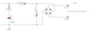
You can use either a 9v battery or lower the tension of the alternator using D9-D10-R14 as show in this schematic:
Adjust R14 in ratio to current consumption.
ie: 10 to 20mA = 2k7 3Watts
Hi,
– Is it input signals on the schematic labeled “X1-1” to “X1-5”? Where are these signals coming from?
Or, can these signals be used as output signals, analog or digital, from PIC16f628A?
– Similar question as from “Loop 26 November 2016”: In absence of 12V battery, but a LV supply magneto coil on the engine- leaving about 14-16Vac. How would that circuit look if 16Vac is connected to PAD2 instead of the battery +12Vdc?
X1-1 to X1-5 are dedicated to the ICSP connector.
ICSP stand for In-Circuit Serial Programming. The software doesn’t use them for anything else
-Use a external bridge rectifier to rectify your AC before connecting it to the DC input !!
16vdc is fine , a LM7805 can handle +24Vdc
Thanks Thierry.
Quotes:”If jumper is ON (meaning putting a jumper, so RB2/pin8 is connected to ground)
CDI is automatically generating sparks without any pickup signal, at a frequency of 50Hz.
(50Hz = 2800rpm for a 2strokes)”
Why do you have 2800RPM 50Hz pulse frequency?
Because I know so:50Hz=50 pulses in one second. 50*60=3000rpm/min
Why only 2800 rpm 50Hz to you?
I also deal with ignition advance delay microcontroller (12F683/8MHz) software.
What is your opinion about it?
Link:https://www.rcgroups.com/forums/showthread.php?1781959-Programmable-Open-Source-CD-Ignition-PIC1840/page92
Thank you in advance for your reply.
Regards nyemi
Totally right. I checked and it’s 20ms between pulses then 50Hz and 3000RPM. (I’ll correct it).Thanks
I didn’t read the 92 pages of this huge thread, but it’s interesting. Personally I’m not a big fan of 8pins PIC as you need some tricks because the lack of availables pins.
IE, I would avoid to deal with analog input to chose between 4 curves, I’d prefer 2 jumpers giving 4 possibilities.
You chose to separate the timer from the power part. It’s a choice but in my experience, people who don’t have enough skills prefer a unique part or ever the simplest way to build one. Good stuff anyway.
Is there any problem using pickit 2 for burning the IC?
Pickit3 is suppose to be faster for debugging, it can work with lower Vdd and must be use for the newest PICs. (ie: PIC32)
but for those midrange PIC16F pickit2 is just fine!
which are the other components needed to drive tachometer
It depends on what your tachometer is waiting for…
In most case, it wait for a 0+12v pulse so you’ll have to add a NPN transistor in common emitter mode
like here.
As Thiery has said the tacho receives a pulse normally of the same voltage in the form of a sawtooth with little duration . This seems to be common on both the tachos I have Honda and Aprilia and I am trying a Yamaha R6 type to make sure that it is the same with ECU tacho out , but although these would look cool on any bike I suspect the ECU driven tachos deliver a 5V square wave to the tacho driver . The NPN common emitter works for both tachos that I have and is likely to be the solution for any tacho that used a combined CDI coil unit . It would seem that any medium power NPN transistor is OK for the purpose ( I chose one at random from my tray) and that output can be used for signal in to the exhaust power valve ECU too for the 2 stroke singles. I chose a medium power mainly because of the additional load required by the exhaust valve ECU but is probably not necessary .
This is a great little kit for any young person into bikes with little experience in electronics and soldering and wants to learn the basics of programming ECUs for which Thierry must be congratulated as this is a very affordable way to start. A Merry Christmas to you Thierry and everyone else !
Hey! Glad to hear from you Malcolm !
Thanks for you wishes, and get mines in return for you and all your beloved ones.
Following our convo, the blackbird stickers have already been printed for version 8
Thanks for this inspirational idea 😉
I’m happily surprise that the NPN interface is enough to driuve the power valve. That’s cool and I regret to doesn’t offer a tacho output anymore on the future version… Hopefully I let 2 output in standby that could be use if I modify the soft.
it’s possible to add input from map sensor to pic micro beside pickup sensor ?..if it possible how to modify the circuits n program?
No it’s not possible. This would need extra componants, different software and even a powerful PIC.
Thierry,
I have built version v7.9 and it worked well.
Now I want to programm on the circuitboard with ICSP connector.
I use Pitkit V2 with Velleman VM203 but there is a problem, the programmer said; “Program Memory is not blank starting at address 0x000000” Also I can not verify the programm.
When I programm the PIC on the Velleman board the programming works well.
Can You help my out??
Jan
Hello,
Bad erasing are often relative to Vpp tension.
-Don’t power up the CDI when using ICSP
-Have you tried “tools >Use VPP First Program Entry” for Vpp coming before Vdd to avoid the software to start?
-If LVP (low voltage programming) is ON, try to play with Vpp voltage going from +5Vdc to +2.5Vdc
if not, check if pickit2 programmer is able to provide a strong +12Vdc Vpp
Thierry,
The option “Use VPP First Programm Entry” did the job, Its working!!
Thanks
Jan
Hi.
I found a bad engine start. In proteus simulator I saw a bug in delay on low frequency. 8 Hz is Ok, but 7 Hz has no any delay. 6 Hz very small delay and so on till 1 Hz. You can see it yourself in your proteus project and sample CDI_16F628_V7.9R11.hex
Hi
You are right but it’s not a bug. At 7Hz (420RPM) the 16 bit Timer1 overflow.
If you really need so low RPM you must slow down the PIC clock by increasing the prescaler value (cell M26)
The new Excel file is clearer about that:
Ok, thanks, i see. I’ll try to play with prescaler value. But this does not solve the problem start engine by kick-starter or by bad accumulator. First flash occurs too early and kicks back. It would be ideal to use a second pulse of pickup coil for the first flash as doing many commutators but it need to change schematic.
Second pulse in the comment above mean negative part of signal.
You can try the new curve_adjust_Excel2010_v79r11c2.xlsm with prescaler=8 and multiplier=100
Can you modify the software to handle the advance of two cylinders with a single micro?
With independent pickup
No, as the web page title says, its a CDI for SINGLE !
From having 2 cyl driven by 2 separate pickups, you can try to use 2 CDI unit. One for each cyl….
THANKS FOR YOUR REPLY
Good evening, is it possible that you can download the source code too?
Hi,
I have built this ignition and it works fine on table, but the bike’s behavior is not too fine…Maybe the ignition timing is not suitable. I’ve programmed the PIC with 36º pickup coil position, but I can’t find any information how much exactly is.
May you know the exact electrical position? 90′ Suzuki DR650. Thanks in advance.
Hi,
I have already checked it. The pickup coil position is 42 degree.
Glad that you sort out by yourself !
There is a VERY interesting explanation on how to calculate the pickup position on page 18 of http://www.yikecx.com/Files/ECOTRONS%20Hall%20Sensor%20technical%20spec%20V1.3.3.pdf
Copyrights ECOTRONS LLC
Bonjour Thierry,
tout d’abord un grand merci pour la qualité de votre site,
j’ai monté votre allumage AC-CDI 16F628 v7.9sur un moteur de 103 allumage électronique, j’ai un petit soucis il ne veut pas passer les 6000t/min, auriez vous une petite idée?
Merci d’avance
Merci !
Classiquement sur les 2T faut vraiment baisser l’avance a haut regime.
Regardez les courbes d’avances 2T…
bonjour voila debutant en electronique j ai quelque soucis pour comander les composant neccesaire je voit sur la liste des differences avec le shema notament la resistances r1 etc et t il possible de recoir une liste plus detailler ou realiser des kit a monter soit meme mon premier projet est pour un scooter suzuuki
merci de l attention portee a mon mail
Bonjour Sebastien
R1 = 15k mais ce n’est pas critique, une 10k convient tout aussi bien!
Je ne vois pas quoi détailler de plus… Tout les composants sont très classiques et répandus.
merci
je vous tiendrai aucourant de ma realisation
Hi terry..till now i’m stil watching up your site trying and trying to understand it,I still wait pickit3 that I’ve ordered from local online store.I hope you can guide me next,u know its a very hard way for me
hi i come back to you, i sorry but the cdi will not function cause my alternator not delivrate a 200v but only 24v (i think) i must confirm,could you eventually make and additional circuit for generate this voltage wiht the 24v comming from alternetor or with the 12 volt comming from the batterie (http://www.abcelectronique.com/annuaire/montages/cache/357/montage021.gif)this shema not help me cause a don’t know the part list to make it
or i have find this https://www.amazon.fr/gp/product/B01K40NK6Q/ref=ox_sc_act_title_1?smid=A1XTJ6FZJZ40TR&psc=1
thinks for your attention and sorry for my english
if you need i cant speak in french that better for me
Hi, Then you need a DC-CDI (to transform +12Vcc into ~200Vac) not a AC-CDI !
The kind of control you must do BEFORE building a CDI not after! 😉
Autrement ce convertisseur 12/220 d’Amazon convient parfaitement. Trop puissant (150w) pour un scooter mais ce modele est bien régulé et il y a plusieurs tensions disponibles en sortie.
Attention il y a un risque de destruction du SCR car celui-ci va mettre en court-circuit le convertisseur lors de l’etincelle.
Hi Thierry, I really liked your device! I collected it and made a curve under your Moto, I was faced with the problem of EEPROM…. I need to tweak the EEPROM like on your photo in the program Icprog ?
or simply type in the 95 values of the RAW data [cells to Q19 Q34] in the ICPROG Eeprom Data screen, quite bothersome…
Hi Maks Thanks!
Yes you can tweak the eprom using ICPROG in Editor mode as I show on the snapshot below:
… or simply type in the 95 values of the RAW data [cells to Q19 Q34] in the ICPROG Eeprom Data screen, quite bothersome…
Thierry, thanks for the quick response! I can’t attach a photo in the comments of your example…after you create a curve in EXCEL, the code in the last line of the EEPROM turned out to 4F 0B 00 02 05 14 09 67 as I understand I need to iceprog in the last line of the EEPROM do so 00 00 00 00 and the next four pairs 14 09 05 67 do not touch?
No worries for the translator.
I don’t understand why you want to modify the eeprom directly instead of modify the Excel.
If you draw a curve while you change the LAST line of eprom, calculations will be wrong! Don’t do that!
ie, the meaning of: 4F 0B 00 02 05 14 09 67
is
02 = number of strokes
05 = multiplier in lowRPM formula (cell I2)
14 = Time for the PIC to make one calculation
09 = Timer1 (max RPM)
etc etc
Each value as a meaning, don’t change them without knowing or you will get a f… mess!!
Change the values in the Excel sheet (tab “Advance_curve” and “advance_at_lowRPM”) and the Eeprom values will change in Excel.
Then copy (or type in by hand) the values that HAVE BEEN CALCULATED by Excel macro into the eeprom.
Don’t invent values that wasn’t in the excel sheet.
I understand you. thank you very much!!! I’m really confused, I translate your text through a translator he introduced me astray…
now I understand everything! I just need to copy the final file to my curve with EXCEL EEPROM and insert it in Icprog…
Hi Thierry! I want to build a device, My question is, 1) Type in the physical position of your pickup in the cell F5.
Example: 36 degrees before top dead center
How do I know position ? any value? I have a Chinese copy of a Honda cub
Hi, You should find this information into the Technical documentation of the bike. Also on forums…
Otherwise, you will have to open the engine and measure by yourself following the method described on page 18 of http://www.yikecx.com/Files/ECOTRONS%20Hall%20Sensor%20technical%20spec%20V1.3.3.pdf
Copyrights ECOTRONS LLC
Hi Thierry
I trust you are well ? A slight accident with complications has kept me away for a while !
Chapter 4 of your link is the most relevant but you can detect the changes with a simple multimeter which will give negative values if you have diodes ,voltage sources etc reversed without going to the length of rigging up anything to most sensors . If you have a water cooled motor your flywheel will generally be flat which will enable a degree wheel to be stuck to the face of it with blue tak . For small flywheels a kids 360* protractor is useful they cost very little . Position the protractor roughly central on the flywheel as close to central as you can . If there are no marks align the sensor with one edge of the magnet on the flywheel . Rotate the flywheel and it will read positive negative or vice versa or go high then low or vice versa on the MM. You now have your polarity . Realign your sensor to the magnet which ever way your rig runs and attach your degree wheel on the flywheel with zero at maximum deflection . Remove plug and place a pencil or something similar down the hole to the top of the piston . Slowly rotate until the piston reaches top dead centre (TDC) keeping an eye on your degree wheel . When the piston goes over the top rock it back to take up slack and establish TDC again by maximum rise of your pencil . Write down the number of degrees rotated from sensor . Retry several times and use the average of all your readings to insert into the BTDC box . With ignition systems that trigger in any other position , e.g. the technique is the same but the inverse of the angle is used as described in the link . You will find that you are close enough to the correct figure to make little difference to your theoretical ignition curve . On this subject I tend to draw a theoretical curve and insert the values by interpolation . If you check out the forums most individuals with programmable systems give their ignition curves freely on graphs for most 2 T and 4T motors particularly the popular ones in various states of tune and this is a good place to start but be a little short on maximum advance and overdo the hi rpm retard a little to stay safe !
I hope this helps those who do not have the ideal setup with all the necessary marks etc . If you are building one of these it is likely you would have a fairly good MM .
Keep up the good work .
All the best
Hi Malcolm,
Long time indeed! I hope it wasn’t too serious…
Thanks on behalf of all the readers for this complete explanation of this trick that works.
Let me illustrate your words with some snapshots of the same technics using a comparator instead of a pencil but a pencil works great too and the protractor stick on the flywheel.
It has been done on a Yamaha 125 DTRE which result in 17deg BTDC
Best,
Thierry
the cdi works fine at idle but when i accelerate the engine it dead soon,and the led blinking like something resetting it,is it caaused by EMI/EMF..what is the solution for it.thanks
Are you sure it’s a reset? Does the led blink 2 times like when powered up?
if yes, EMI is a electromagnetic energy transmitted from one device to another by radiation or conducted paths.
Lower the energy:
Use a sparkplug cable equipped with a internal resistor that limit the voltage peaks when spark occur
conducted wires:
To limit the spikes to jump to all nearby cables, twist the 2 cables that power the CDI and add a ferrite choke around.
Do the same with the pickup wires.
Radiations:
Use a metal enclosure connected to ground to block electromagnetic fields.
thanks.i will try it.yes i am sure it is resetting.the leds blink two times like at powered up.,it is a must to solder the 100nf ceramic cap acros vdd and vcc under the microcntrl socket like shown on the pcb layout?
And adding 5,7 ohm resistor before 7805 regulator?
becouse it is what i haven’t done..
If you remove all protections don’t complain of reset !!!
ha ha..yes.. that is my bad,i’m too careless..thanks for your quick attention
and respons.,
best on you
For any of the 16f628A units, would it be possible to use a hall effect input in place of the captor coil. I saw an input to the micro as a square wave which appeared as a processed signal from the captor coil and this is why I ask.
Use would be for miniature model engine as space available favours the use of the hall effect pickup.
Thanks…Jorgo
Absolutely ! While sure the hall effect sensor give a good and clean square +5v signal, then you can remove all the parts that shape the pickup signal: Q1,Q2,R10-11-12,D5,D8,D9,C7. You will free up some room…
Th.
Hi Thierry,
great efforts with you project, I’m loving it. Made two overall, one early v6 version, and one latest v7.9. For this latest build, I intended in using the CDI on an old school point ignited two-stroke. The plan was never to use the 200V tension, but rather use the thyristor to replace the points. I’ve added the pickup to the system, and I’m generating successful positive first signals to trigger the circuit. However, for some reason couldn’t make it all work. Tried with different coils, with no success. To clarify, PIC is booting, running on the bench and all, but would not throw a spark.
Basically, I’ve removed the following components from the PCB: D6, D7, R8, C8. In addition, C2 has been removed and replaced with a jumper wire. Coil was connected to constant +12V feed, and grounded through thyristor (PAD3 disconnected). Curve adjustment called for a 1ms output duration, and if I’m not mistaken, PIC drives the thyristor closed and opens it to throw a spark. This should cause the collapse in the coil, and induce a spark, but instead, I got an overheating coil and an overheating thyristor (burned one of both in the process).
Having failed to succeed, I’ve then fed the thyristor from RB5 (inverted output), and got all working on the bench again. However, coil still overheating and no spark.
Finally, I went “all in”, and connected the coil to both +12V and GND, and attempted to throw the +V to ground through the thyristor, for a duration of 1ms. I was willing to sacrifice the circuit, and it basically lasted only one cycle. Thyristor cracked open, and I’ve finally given up. PIC still outputs though. 🙂
I’m hoping for some of your wisdom, although I’ve modified your design. I hope I didn’t make a mess in this write-up, so please share your thoughts.
Regards,
Rikko
Hi Rikko,
Thanks for this long description, I appreciate it.
Well, you certainly have understood that replacing a old point system mean using a TCI not a CDI.
See the link “TCI is not CDI” in my FAQ page…
>and if I’m not mistaken, PIC drives the thyristor closed and opens it to throw a spark. This should cause the collapse in the coil, and induce a spark,
That’s were you are wrong! PIC drives the SCR ON, but a SCR CANNOT BE TURNED OFF by the Gate. It turns off only when the current flooding between Anode to Cathode goes null or negative.
With your wiring, the PIC fire the SCR, the SCR connect the coil to the GND and you get one spark, then the SCR keeps turning ON and the coil overheat until it blow up.
Replace the SCR by a Power Mosfet transistor (ie: IRF740 is 400v/10A with a protection diode inside)
Thierry
Hi Thierry,
Ha! Of course, you’re right. I knew i was not seeing the forest from the tree.
I will definitely try the IRF you proposed, but for the record, I’m also going with an idea of stepping up the voltage by means of LT1073.
I’ll keep you posted.
Thank you so much,
Rikko
Hi Thierry,
Quick feedback for you. I’ve tried the IRF740, and found that it won’t open fast enough, if driven from PIC’s 5V output, due to “high” load. I’ve then added a open collector buffer, to increase the gate voltage closer to desired value.
I’ve got the spark now, however I’m struggling now with EMI. Measured across the PIC voltage supply pins, up to 80Vpp, with the period of 45nS. To tackle this problem, I’ve made a simple RC filter, between the 5v regulator and the PIC. With this giving no result, I tried adding ferrite cores, system is running from battery, but still I have significant conducted EMI. I’m thinking of adding another filter, this time a 3rd order LC, just need to pick a right place for it.
I’ll give you another update once I’ve solved it.
Thanks,
Rikko
Rikko,
EMI is THE major issue, particularly with TCI because of the coil connected to the same +12Vdc than the PIC !
-Apart from all the good filtering RC cell, ferrite, capacitors, you can try to:
– add another 25v zener diode between D and S
– a 100nf/200v between D and S
– a fast diode in // with coil, anode at D, cathode at +12v
Good luck
Th.
HI,
I have seen that schematic and part list doesn’t match for this devices:
R1 15k ( sch 10k)
R2 10k (before was 1k)
R7 330 (sch 360)
R9 10k ( before was 470k, sch before 4,7k)
Can you please update correct values and maybe explain for each does it matters value change and how, I would appreciate it, thanks
Hi
Well seen!
I have corrected the partlist.
R1 15k => 10k just to simplify and have a uniq value for R1,R2,R9
R2 10k (1k was too low with some slow SCR)
R7 330 (360 is the standard E12 value )
R9 10k (This one could need to be change according to the pickup. Extreme values met were: 470k to 4,7k)
Bonjour Thierry,
do you know if someone adapt your CDI on a 125 DTLC (question behind is does someone used it with YPVS valve)?
Merci
Bonjour,
Version 7.9: I don’t know but Version 6.7 has a curve made by a DTLC125 owner.
About YPVS I already talked about that in a comment above.
A simple Control+F will take you to my answer.
😉
Merci Thierry,
je pensais avoir lu tous les commentaires mais celui ci m’a échappé.
Could you please push my email address to Malcolm Robartes.
I will try to discuss directly with him about YPVS.
Hi Thierry, with pushed with a problem when creating a curve …
on my moto native angle of ignition 18 °, do I need to write 18 ° in cell F5 ??
4) Type in the advance you want for each RPM in column F. + with the position of the sensor?
Example F5 = 18 ° + 4) Type in the advance you want for each RPM in column F. (10 °) = 28 ° advance angle? I understand correctly?
Hi,
No! In the XLS you can read 52degrees in F5 and 10 to 14degrees in column F.
Then 14 is not 52 + something!
You fill in the real advance values you need in column F (ie 10°) and the processor take into account the pickup position you wrote in F5 cell.
What you call the “native angle” or I call it “pickup position” is the Top signal.
The pickup gives a Top signal and processor make all the calculations to send a spark at the good time.
If your “native angle” or “pickup position” is 18° then the MAXIMUM ADVANCE can obviously only be 18°
In other terms, the so-call “pickup position” is the actual MAXIMUM ADVANCE of your bike.
Thank you! I got it)
You can make a sample of the file Etsel for degreses 18 °? it’s so easy for me to understand you. Thank you
my email: [removed]
Hi Thierry, i had some problems with my pickup pulser, my pulser output only had 0.8-1.3v, then it cant be triggered pic?
Do you had any schema for steping up my pulser output to >2v for triggered pic?
Hi, Are your sure? Did you measure with a scope?
If so you can add a amplifier with a FET (ie: BS170) like the one on the left:
http://kudelsko.free.fr/articles/mosfet/mos.gif Or a simple LM741 operational amplifier.
Yep, i already tested with scope.
My stock pulser only had single wire with output volt range 0.8-1.3v.
I will try adding the amplifier before capacitor to pic,
Thank you for response i will update the result immediately.
Are there any recommendations on wire sizes or types to connect this to the rest of the ignition system in an AC application?
I was able to use a laptop sound card oscilloscope to look at the signals. I followed this http://homediyelectronics.com/projects/howtomakeafreesoundcardpcoscilloscope/ but added voltage dividers to step it down to 10 V prior to the circuit on the page. The recommended software works in Linux with WINE. There is also a Linux specific package called Xoscope.
Apart from Xoscope, there are a bunch of other softwares and hardware already listed in my LINK section 🙂
0.75mm2/18AWG or 1.5mm2/15 AWG are the most appropriate.
I started building the “no battery” version with the purchased board. Per the instructions further up, several components need to be added. (I have zero experience with PC boards so this is a learning experience.) Should I drill holes for these extra components or maybe open up exiting holes such that two components go in the same hole or is there another recommended method? It looks like one joint will have to be bridged across the top. Recommendations, guidelines or examples would be appreciated. I also have just one trigger but it does not look like I need to do anything different on the board. Thanks
by further up, you speak from the scheme extract above?
Usually if the components to add are small, we sold them on the bottom face.
Here R14 is 2k7 3watt so you’ll have to drill extra holes for R14,D9,D10.
You can also move them + D5 and D6 and a small external PCB
You can use either a 9v battery or lower the tension of the alternator using D9-D10-R14 as show in this schematic:
Yes that is the one. I’ll try extra holes. Do you also clean off some of the board coating to create a pad? Would that be some kind of chemical clean or mechanical scraping. Thanks
Yes, you can gently rub with a drill attachement then drill the holes and finally clean everything with diluent.
Since PAD2 becomes unused, could that portion be re purposed with no battery?
1. R14 between one of 2 extra holes at left of C2 to PAD2.
2. D9 between PAD2 and PAD8 (ground)
3. D10 replaces D2 (actually they are the same value)
I have a picture but don’t see how to post. Sorry for all for the questions but this is an interesting project. Thanks for posting and maintaining this.
Ok, I visualize it. Right you can do it this way!
I’m slowly working my way through but have a couple of more questions.
1. Where can I find the heat sink? I have been on Digi-Key but do not see anything like what is in the picture.
2. I bought a PICKIT 3 for programming but do not see how it connects to the board. I will install the PCB connector on the board but it has 5 pins while the PICKIT has 6. It looks like it would almost plug direct into the PCB connector but not quite. (I bought a 6 pin connector by mistake.) I probably need a cable. Where can I get one? It did not come with the programmer.
Sorry for so many question but I’m a beginner. Thanks!!
Well Dan…
in DIY Y stands for Yourself, that’s imply a part of active researches…
Even as a beginner, that’s how we all learn…
1) Where to find a heatsink in your town/country : Don’t know.
2) If you’d take time to compare the PicKit3 pin out again the schematic of AC-CDI v7.9 https://transmic.net/16628_v7/sch_cdi16628_v79.pdf
you’d see the connection scheme is pretty straightforward ? isn’t it?
Hi, great job! using the avr atmega168 20mhz the project freezes .. probably by the emission of EMI noises. Would decreasing the clock solve? Is there a book dealing with the design of ignition modules? thank you
Hi thanks.
Slowing the clock could improve. You have to bench your code with a pickup simulator first to avoid EMI and when it’s rock solid
test it on real.
Follow the advices I gave above.
Dear ,
is it possible to make the pulse at pin 1 ( the trigger of the thyristor )longer to about 5 msec , what is about the normal time for a classic ht coil , then it must be possible to use the pic for a TCI ignition for older 1 cyl 4 stroke machines . Then there is only need of the pic and a good IGBT .
Thanck You
Hello,
Why not… but the switch into a TCI is up to you!
Use cell M29 in the new Excel file curve_adjust_Excel2010_v79r13c3.xlsm in the download section above.
Keep in mind that currently in CDI mode the PIC ignite a spark at the RISING edge of the 500us pulse.
If you drive a IGBT and a TCI coil, the spark appear at the FALLING edge of the 5ms pulse.
Take that into account in the Excel file !!!
Also notice that 5ms equal 12000RPM, as the PIC need about 100us to do the calculations, the max RPM will fall to around 10000RPM
Dear ,
high RPM is not a problem for an old 4 stroke bike
As I good understand it ,if I use a hall sensor , the pic is triggered with the rising edge of the pulse , the SCR is triggered with the rising edge of the delayed pulse from the pic , but my pulse must begin 5 m sec earlyer ( I need 5 m sec to load the coil ) and the falling edge of my pulse must come at the time that you have the rising edge , is that possible in the exel file . I was thincking to do that with hardware , but i thinck that this is not possible
And 5 msec is not the same amount of degrees at every RPM
Do you see a solution for that ?
Thanck You
you understood it well.
As I told you, switching to a TCI is up to you…
It is not enough to replace the SCR by a IGBT!
Not only the Excel file must be different but also the software to take into account the varying dwell time that must append BEFORE the spark.
I offer software for CDI, not TCI.
hello ,
I have made a litle calculation , for a dwell time of 5 msec it takes
30° at 1000 rpm
60° at 2000 rpm
90° at 3000 rpm
Is that correct what I say ?
If it is so , I can forget it , because I can not make a program
your calculations are right!
That’s why TCI software turn the coil ON before the pickup signal…!
Bonjour Thierry
Je vous remercie dans un premier temps pour votre site et votre partage. J’ai réaliser le simulateur qui fonctionne très bien. Je suis entrain de réaliser le AC-CDI 16F687 et je me pose une question sur le schémas: je suppose la diode D7 doit être une diode de roue libre pour protéger le thiristor T1 mais comme elle montée, elle doit court circuiter une alternance de la sortie 200V de l’alternateur. J’ai juste? Si oui, cela ne risque pas de griller la diode ou l’alternateur? Merci d’avance.
Bjr Thomas,
Oui le simulateur fonctionne trés bien mais la version 3 est encore plus pratique
😉
Effectivement D7 a un double emploi avec D6: proteger le SCR et CC l’alternance negative. C’est un montage commun a beaucoup de CDI.
La resistance interne du “charging coil” est de 200ohm, donc un courant theorique max de 1A si l’alt. produisait 200Vac
or le pont tient 1.6A et comme la diode devient conductrice a 0.6v, la tension de l’alt n’a pas le temps de monter.
De toute facon l’alt est aussi court-circuité par le thyristor 100fois par seconde 🙂
Hey Thierry. How can I contact you about shipping information? Is the shipment registered etc.
Oups, the Contact link went away in the sidebar menu of posts!
It’s back again sorry for that.
Methods of shipment are written during the buying process.
Ready to use units are send with tracking numbers.
(French postal fees for Europe are 4.30€ or 5.40€ depending on weight)
Other items (pic, pcb) are send in simple letter.
I don’t offer registered mail with return receipt because prices are insane!
(6.20 to 7.20€ for Europe)
Hi!
Sorry for the stupid question,buthow can correctly measure the pickup position (BTDC)
What range is accepted?
Thaknyou for your help.
Peter
The range is since: Version 7.9R12c0:
[soft.] RPM limiter. Can handle pickup position upper then 50deg.
As long as the pickup position doesn’t make any errors in the Excel file depending on the curve you want, there is no fixed limit.
Use a degree wheel on your crankshaft (or magnet/rotor) to find out pickup position in degrees BTDC. Also you can use timing tape. It is how many degrees early your pickup spits out a pulse before the piston reaches TDC (top dead center). Theoretically, range should be 0-360 degrees, although I dont know about this CDI’s software limitations 🙂
Totally right Lukas!
@Peter: you can also read Malcom’s comment N°1240 and 1241
Hello.
Congratulations on your website renewal.
After renewal, there is no excel v79r13c3.
Did something wrong happen?
Thanks Koshi for letting me know about that miss!
Yes some updates have been lost during the migration… It’s never easy as pie!
Now it’s corrected.
Hello thierry, eh made your ac-cdi and it works perfect on series bikes, on competition bikes the spark is off … I already tried to increase the capacitor to 2.2 uf and I had a small improvement but it still lacks. The original ac-cdi has a very good blue spark.
Thank you very much for your contribution.
Hi Ramiro,
I’m glad to hear that it work perfectly!
For a race unit, you should try to add a bridge rectifier between charging coil and CDI in order to move from a “half rectification” to a “full rectification“. The tension loading the capacitor should double… 🙂
PS: You need to have a STRONG SCR if you do that as the tension can reach high level….
Thanks for answering. Use SCR bt151 and 400v capacitors, should modify the stator since it is referenced to GND ???.
can you add an auxiliary limiter, double auxiliary advance map?
BT151-what? use at least a BT151-800
400v capa are great.
Of course you should modify! Stator cannot be referenced to GND !
Unfortunately this PIC is not big enough for 2 advance maps.
And I will keep features aside for the paying version, not the free one.
business is business 🙂
I think it’s great, it’s going to be a good cdi with those thierry success features ..
Then I tell you how I work with the modifications.
Hey Thierry. As I understand, you’re planning on making a similar CDI to 16F628 v7.9, but with a more capable PIC ?
No no!! v7.9 will stay as it.
I was talking of evolutions reserved for v9 only, not for the free version 7.9
Hello Thierry good morning.
I am writing to tell you that the CDI works perfectly with the bridge rectifier, but I must manage to operate the CDI with half wave rectification.
There will be the possibility of making the variable pulse width output for the SCR from 0rpm with 5ms up to 14,000 rpm with 500us. If the modification of the source code is not possible, what would you recommend doing with the hardware?
Thank you very much.
Hello,
It should be faisable to change the source code for a pulse width from 500 to 5000µsec.
I’ll look at that and contact you by MP for some tests…
Th.
Thank you very much for the reply, I await your reply to my thierry email.
The new version v7.9R14C0 that you have tested is now inline with the option of “Auto” Dwell.
The pulse to SCR is automatically adjust from 5000us at idle to 500us at high rev.
I made “AC-CDI 16F628 V7.9”.
SCR used “SCF25C60”.
It idles when I wear an engine and it is stable, but cannot blow.
The inside, a high turn do not turn around.
Because there is only one pickup, I am connected to 36 degrees.
Does a circuit or the program need a correction?
4st Suzuki
Ignition time: 27BTD ℃ /1700rpm
I want advice.
What input are you using: for positive-first signal or negative-first pickup signal?
For negative-first pickup signal
suzuki
If you want help don’t play with us and give ALL informations !!!
Suzuki what? model ? Cubic size?
Advance curve you’ve programmed:
how many adv at 1000,2000,3000,4000,5000,6000 ?
Thank you for a reply.
Sea bass GSXR50
50cc
Pickup position (BTDC)45 degree
The progress curve that I programed:
1000rpm15 degree, 2000rpm20 degree, 3000rpm23 degree, 4000rpm25 degree, 5000rpm28 degree, 6000rpm30 degree
Number of cylimder:1
strokes:2
prescaler:2
output width:500us
In the case of one, how does a pickup coil set [Advance at low RPM]? In addition, is there the change of other setting again?
I don’t understand your last question!
Pickup position is probably wrong.
This 50cc should use around 20degree BTDC. Check this out !
Change the “multiplier” in [Advance at low RPM] tab to get around 5 deg of advance.
The timing curve should be like :
lowRPM: 5deg, 1000rpm: 10deg, 4000rpm: 20deg, 8000rpm: 15deg, 120000rpm: 10deg,
Number of cylinder:1
strokes:2
prescaler:2
output width:500us
Thank you for a reply!
I test it by an upper program.
In addition, my motorcycle is different from the photograph that a pickup coil had you put it up.
I am glad when you can confirm it because you put up an illustration.
https://d.kuku.lu/3c41513361
In this case is BTDC 45 degrees?
Actually it can be 45° or 55° BTDC.
You said you use the negative first position (Suzuki), that means the CDI use the Negative pulse which is supposed to be the first.
If this NEGATIVE pulse appear when the RISING edge of the tab pass in front on the pickup: you use 55°
If this NEGATIVE pulse appear when the FALING edge of the tab pass in front on the pickup: you use 45°
Check the polarity of your pickup (Negative then Positive or the opposite) with a ANALOG multimeter (in milliAmp position) while kicking.
Like that:
I thank for support.
When the upper end of the tab passed before pickup, a negative pulse is displayed.
The curve that I programed:
BTDC 55 degrees 1000rpm: 10deg, 4000rpm: 25deg, 8000rpm: 30deg, 120000rpm: 20deg
BTDC 45 degrees 1000rpm: 10deg, 4000rpm: 25deg, 8000rpm: 30deg, 120000rpm: 20deg
I tried the above, but it idles, but a high turn does not turn around.
A plug becomes black and feels that I do not spark by the high turn.
When V of the pickup coil is less than 2V, what should I do?
I use V79R14, software check sum of Icprog and Pickit3 v3.10 becomes [566F], is it all right?
Thank you very much for your help.
Hi,
>When V of the pickup coil is less than 2V, what should I do?
You need a OSCILLOSCOPE to measure properly.
A multimeter is too slow so the value you see is wrong.
if it works at idle that mean the pickup voltage is OK
>A plug becomes black and feels that I do not spark by the high turn.
HOW ARE THE LED ?
D3 light at each pickup. No blink = no pickup signal
D4 light at each command for a spark. No blink = no sparks
Black sparkplug just mean bad combustion
>I use V79R14, software check sum of Icprog and Pickit3 v3.10 becomes [566F], is it all right?
Pls reload the software V79R14C1 . Now the checksum is 566F (not 366F)
I think the values you programmed are wrong.
Try TOTALLY DIFFERENTS VALUES, ie BTDC 20deg than 70deg and see what is better…
Change the “multiplier” in [Advance at low RPM] tab, try big advance, then try big retard and so on and so forth….
After confirming ignition time with a light in a timing, after going over 3000rpm, change time acts violently.
An angle did variableness definitely to 3000rpm.
The LED flashed on and off.
Remove kill switch “D8, C9”.
Use 1000us output width
Replace D4 with diode 1n4148. Replace R7 with jumper.
Replace R9 with 4.7k.
Replace R12 with 680.
Add 220nF in parallel to C7.
Use spark plug with resistor or cap with 5k resistor.
Some of these possibilities helped me with problems at high RPM.
Thank you for the feedback for a Honda biz 110cc
Ramiro, a reader who built a ACCDIv79r14 for his Yamaha Mint 50cc 2strokes with a pickup at 57° BTDC
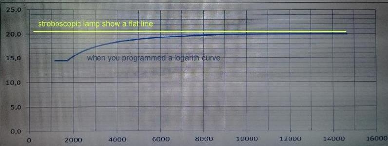
didn’t understand why he needed to program a LOGARITHM-like advance curve to see a 20° FLAT curve with his stroboscopic lamp ?
It’s a interesting remark and worth a explanation here for everyone…
It’s normal. This is due to the pickup coil that ALSO provide advance when RPM changes.
So Ramiro had to compensate this extra-advance by more or less advance into the processor.
It appears with ANALOG VR pickup technology where the voltage and timing change with RPM.
It doesn’t appear with DIGITAL pickups (like Hall effect sensors or Opto sensors).
Something to keep in mind when it comes to setup your advance curve !!
This also shows how much a strobe light is essential if you want to tune the engine seriously!
Hi, from my point of view it is not logarithmic, but more something like a RC curve.
One question I have:
What is the function of C9? Make the triggering faster?
I would remove this one (or add 47 ohm in series), because it is responsible for peak currents (higher then maximimal current for the microcontroller pin) for a short time when starting the trigger puls.
The microcontroller sees only D4, C9 and C5 in series. This will results in high peak current during changing levels on RA2.
C5 is only to prevent false triggering of the thyristor. I would propose to do a test with removing this one.
Hi,
Exact! C5 and C9 have been removed in V9 for those reasons. 🙂
And indeed it’s like a T=RC curve. Well seen!
Hi Trierry,
I have an other idea.
Currently R2x is 10k, but intelnal in a thyristor and a triac is always a low ohmic resisor inside (depending if is is a sensitive gate type or not, in the range of 70-300 ohm). So R2x of 10k has no real function then.
The snubber sircuit R8 and C8 are there to protect the thyristor/triac agains high dV/dt during commutation.
According the datasheet of the BT151 maximal dV/dt it typical 130v/us with open gate (minimal 50v/us).
When Rgk (in our case R2x) is 100ohm dV/dt at communtation limit is increases to 1000v/us (minimal 200v/us).
I didn’t do measurements yet, but I can imagine that we don’t need a snubber circuit any more when we lower R2x to 100ohm.
This saves room on the PCBA, but we need a little more trigger current for the thyristor.
After writing this down I realise that the removel of the snubber circuit will generate more EMC-RFI.
So at last it is NOT a good idea anyway.
In that case we only save space by removing R2x. 🙂
I discovered you web page 1 week ago and I really leaned a lot with the help of you designs about spark designs 🙂
Thanks.
It’s a bad idea to remove the snubber in term of parasitic noise, EMI indeed, it could freeze the processor.
Regarding R2, You could certainly remove it if you exactly know which SCR is used and the spark coil characteristics.
But as this CDI is build over the 5 continents, many differents SCR are used not to mention coils.
So it’s safer to leave this pull-down resistor on.
Th
Hello
I have a Suzuki XF650 Freewind. I don’t know the CDi spec but it’s normally like the DR650 post 96.
Is one of your CDi compatible?
Hello,
You mentioned: Suzuki XF650 Freewind. 1 cylinder 4 strokes from 1999.
Spec says:
Electronic ignition (CDI) => Note: It can be AC-CDI or DC-CDI
Generator coil resistance: 05-0.9ohm Y-Y => Note: So it should be AC-CDI
Pickup: 170-256ohm Bl-G => Note: So it’s a external pickup
Given that you can use:
– the old one ACCDI v6: https://transmic.net/2016/07/19/ac-cdi-suzuki-dr600/
(This version is obsolete and doesn’t allow the user to program a new curve. Also need to reverse pickup wires)
– ACCDI v7: https://transmic.net/2016/11/23/ac-cdi-16f628-v7-9/
(This version is free, it use 2 embedded transistors to reverse pickup. Need a external programmer for the microprocessor)
– ACCDI v9: https://transmic.net/2017/12/29/ac-cdi-v9/
(This version cost 74€, it use 2 embedded transistors to reverse pickup, the microprocessor is programmable on board, on the fly, wirelessly.)
First you should check that the charging coil, ignition coil and both pickups are OK
Th
Pingback: FAQ – Transmic CDI
Mil gracias Thierry anduvo muy bien el cdi en una moto lifan 110cc. copia de honda . Desde Argentina muchisimas gracias por este desarrollo al compartirlo al mundo , ya que este tipo de circuitos y programas es muy limitado!!! Saludos!
Cool Daniel!
Thanks for letting me know that it works great on this monocylinder 4strokes 110cc.
So it should work also for Lifan 88, Lifan 108, Lifan 110, Lifan 125, Lifan 140, Lifan 138, Lifan 150
You are right there is not much free resources for DIY CDI.
Th
Dear Thierry!
Is there a way to purposely change the rev limit to a certain value during operation (e.g. with a switch)? For instance, lowering the rpm to limit the top speed of the scooter. It would be useful in certain situations .
Hi,
You mean “legal” ??
It’s possible to use JP2 to activate a rev limiter but it will not be during operation, way too dangerous! But tested at the startup.
Let me look how to change the code and XLS…
Th.
You got me there. 🙂 I didn’t described exactly the “way” I wanted the rpm limiting, indeed. 😀
But yeah, I’m of course interested in the potential and the oppurtunities of this clever circuit.
I am very thankful and I feel so honored that you are trying to find a solution to my problem.
PS.: I was also thinking about leaving the original CDI in the scooter too and trying to switch between them (between Yours and the original) with some kind of relay, or something. Because the original CDI is limiting the rpm.
But I don’t know whether Your or the original CDI would tolerate it. For example to switch the CDI back to the system at 6000 rpm.
Version v79r17c0 now include this feature of rev-limit.
Enjoy !
Thank you very much Thierry, you are awesome!
Dear ,
I have 2 questions ,
At startup the led D3 flashes 2 times and then goes off , that works OK , after that iI give signals from a hall sensor , they are exact 0 V or 5 V,, the pic works , I see the pulses on pin 1 and the led the led D3 flashes , that is ok , but the led D3 goes on and stays on it does not flash . What am I doing wrong ?
In the text and the schematic of the AC CDI , can I see that there is a 20 kHz signal at pin RB1 ( pin 7 ) but on my pic , the signal is at RB3 (pin 9 ) , or am I wrong ?
Please answer me ,
Thanck you
Hi,
Exact! I have changed the 20 kHz signal from RB1/pin7 to RB3/pin9 from version7.9r15 without changing the text and the schematic.
I will bring it back to RB1 on the next version this month. No big deal.
You say:”the led D3 flashes , that is ok , but the led D3 goes on” but don’t tell what is the trigger of this change of behavior?
Is it when you increase RPM ? after some time at idle ?
As I wrote and the description:
If LED D3 stay always ON, that mean pin10 is always high! => Measure pin10 and try to lower R9 value from 10Kohm to 1.8Kohm or less according to your pickup…
Is C7 a 10nf (no error?) You can try without C7
Simple question:
What is the default output level of your Hall sensors?
Th.
Hallo Thierry ,
I thinck that I have found the solution ,
this afternoon I have made a new hall vane ( B ) , that is the inverse of the original vane ( A ) , the time that the signal is High , is now very small and the low time is long , and the led D3 flashes now at the frequency of the hall pulses .
Can you tell me what is the best time for the pulse so that I can make a one shot multivibrator between the hall sensor and the input of the pic and can you perhaps help me to make that multi ,
I have made some pictures , but how can I attach them here ?
Hello Gerard,
(You can’t attach file here.)
That’s exactly what I wanted you to find by yourself!
I though about your story and the ONLY explanation is the the default level (the level of the hall output without any magnet in front of it) was high.
It’s simple: The LED is high when the pickup of the hall sensor is high.
The CDI wait for a signal like that:_____-_____________-__________
and your hall gives the opposite:
----_---------------_-----------
The duration of a VR (variable reluctance/coil) is 10°
A hall is much lower. I don’t know what exactly the minimum must be but I think a HIGH time of 5degree is safe.
Regards
Thierry
Dear Thierry,
(I didn’t have the chance to build a test bench yet, so I am experimenting directly on my bike.)
In my setup, every corresponding cable is connected to its proper place, but the spark plug is taken out from the head, and connected to chassis ground. Then I rotate the crank with a battery powered drill rated to max 1400rpm.
Then I turn the ignition on, Led D3 flashes twice and when I turn the engine over with the drill, both of the leds flash properly and my oscilloscope records the same signals on Pin 10 and Pin 1 as you have shown in the picture above.
BUT when I insert the spark plug in the head and start the engine, the oscilloscope at Pin 1 shows 2 or 3 output signals for only 1 trigger pulse at Pin 10. Moreover, the engine can only idle, and if I turn the accelerator the rpm doesn’t increase but some knocking sound occurs.
If I power up the circuit with a separate 9v battery and turn the ignition on after one crank with the drill, Led D3 stays on (doesn’t turn off) and if I crank continuously the oscilloscope shows a almost constant 5v, and if I stop cranking it goes back 0v but Led D3 stays on (sometimes turns off).
AND if I don’t turn the ignition off (so one end of the alternator disconnects) the oscilloscope shows correct values at Pin 10 and 1 while cranking the engine (in this case there is no spark at the spark plug of course.
What do you think, where should I start troubleshooting?
P.S.: Some additional information which you may find useful:
-Yamaha 2 stroke 50cc scooter with one pickup (has a small 12v battery)
-Positive first pickup signal (measured with oscilloscope)
-Pickup position is at 75 degrees before TDC
-In the excel sheet I changed F5(pickup position) to 75 (although it says “increase cell J5 eventually” no matter what I change but everything looks Ok) , the advance at low rpm to multiplier 22 and J5 (time step) to 40.
-In column F I didn’t changed the advance values, so 14 degrees are set
-The kill switch pin is not connected because my ignition switch is operating in a different way: it is closing one end of the alternator coil to ground when ON and opening it when OFF.
Hi,
>the oscilloscope at Pin 1 shows 2 or 3 output signals
That mean the PIC see 2 or 3 INPUT pulses!
This comes from EMI noise from the high voltage side of the CDI.
These pulses have a very rapid current change (dI/dt) which generates an electromagnetic field around.
Spark plug MUST have a noise suppressor inside. There are resistive spark plug lead.6 to 15k.
>Led D3 stays on
As I wrote in the blog and in this comment:
If LED D3 stay always ON, that mean pin10 is always high! => Measure pin10 and try to lower R9 value from 10Kohm to 1.8Kohm or less according to your pickup…
Th
I want Board layout.
Thank you.
PDF is in the Download section on the top of this page.
https://transmic.net/2016/11/23/ac-cdi-16f628-v7-9/#download
Kindly mention tachometer connection schematic with additional components to pin 11 of pic 16f628a
You may find some more details here: Duty Cycle Converter
Hi,
I´m struggling with the programming of the PIC, I have tried it in Icprog, PICKit and MPLAB.
PICkit gives me the error message “no device found”.
Icprog says “verify failed at adress 0000h”
PICkit itself seems to work it shows that its connected.
I have also tried to power the pcb externally but without success.
Do you have any idea what could be the problem?
Thanks and best regards, Björn
Hi,
How do you program it?? With what device?
Th
Whit PICkit3
and PICkit3 programmer is connected to a standalone board with ZIP socket or to ICSP ?
Says everything if you want me to help, don’t wait for me to guess what you are doing!!
If ICSP search above in the comment section, I already advice what to check.
Sorry, I´m not very familiar with Programmers like PICkit, I was only working on Arduino so far.
I have connected it via ICSP with the PIC plugged into the PCB.
Unfortunately I don´t know what other informations could be helpful.
Thanks.
I won’t go much into ICSP as it’s not the subject of this blog.
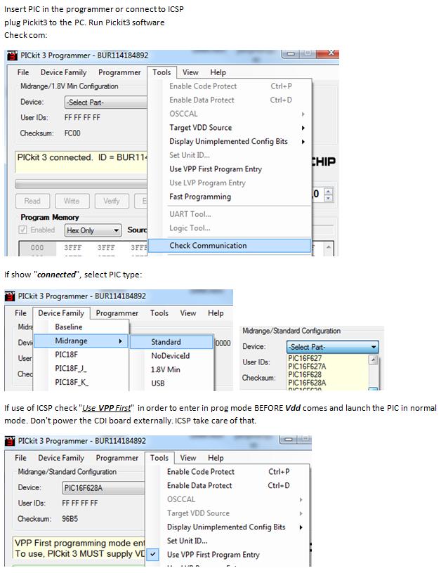
I suggest you to learn about it. You can think there are a lot to master but: Are we Geeks or not?🙂
Arduino boards have a bootloader in them. It brings a abstraction layer that hide the complexity. PICs haven’t!
To go to program mode, some pins must go to some level in a special order. That’s what ICSP and PICkit3 do.
If you power up the CDI, it runs its own software, that’s it!
If ICSP come second, it won’t speak with PIC as it already runs its software. Too late!
Also read: Troubleshoot Pickit3 and try with another known good PIC.
Hi Thierry,
thanks for the help with the PICkit.
Seems like something is wrong with my PICkit clone.
When I measure Voltage btw pin 2+3 I only have 2,47V.
When I enable I/O and measure btw pin1+3 I also have only 2,52V.
The logic analyser also shows no reaction when I trigger one of the channels.
I have now ordered a PICkit2 and hope this works better.
Regards
Sorry, I have to take everything back, I had adjusted the wrong voltage on the main screen, was just to early in the morning 😉
Now I also have the reaction on analyser.
Should the Voltage for the PIC16F628 be 3,3 or 5V?
If it is 3,3V would 5V damage it?
That’s what I thought! Try to FORCE “VDD Pickit3” ON at 5v
The answer is shown on the scope trace for 16F628 in the PDF… 😉
Clones are lottery…
Hi Thierry, Happy new year!
I am hoping you can offer a bit of education for me. Keeping in mind I am considering various options for upgrading the generator/ignition for the Gilera I am restoring.
If you have a spare moment take a look at this item on aliexpress: https://www.aliexpress.com/item/32858721874.html?spm=a2g0s.9042311.0.0.46ba4c4dvt0AaZ
This gy6 11 coil stator has what look to be 2 capacitor charge coils that seem to be feeding a single red/black output wire. The rotor has 8 magnets. Dimensionally this unit is very suited to mounting the gilera engine however I am unclear why the 2 charge coils.
Have you any thoughts or experience of a setup like this, particularly how it would affect the functioning of your accdi unit ?
best regards
Thanks, Happy 2020 !
So a 11 poles stator with a 8 magnets rotor?
The flywheel takes one full rev to charge the cap.
With one coil you’ll get 8 pulses/rev to charge the cap.
With 8 magnets passing over the 2 CDI charging coils you’ll get 16 pulses/rev to charge the cap. That’s all !
Some CDI don’t use external pickup and “count” the charging pulses. Those would care as it affect the timing!
Others and mines waits for the magnet over the flywheel passes by the pickup coil to get the signal and compute the timing based on the engine speed from there.
Those don’t care.
What is critical is the location of the pickup and trigger magnet in relation to the key on the flywheel.
Th
Hola Thierriy Feliz Año Nuevo
I have just finished the CI and I will install on the IC-Prog the v7.9 R19 c0 firmware
But I find a problem and it is the following when I copy the Excel file created in intel format 8Hex I put it in an archovo <txt and I pass this file to hex but when I am going to put it in the IC-prog I see that it does not have the same format and I have tried to esqurivir but the first line is shorter and then the following lines are longer and do not enter the line.
Could you explain this to me why and how it is done.
Do you have any video of how to pass the IC-Prog
Thank you very much Thierry
Translated with Google
Hi Jose Luis,
I added a video above as suggested to show how to merge firmware and data in Icprog.
Hi Thierry, I have just built this cdi and purchased the software, but i am having trouble with programming the pic. So far I have bricked 3 16F628A chips trying to program and they all failed and now are unrecognisable to my pickit2 programmer. I tested with other known working programs which burn and run fine then tried your software and same result of programming failed and chip not recognised. I have tried icsp and burning offboard in a socket with same result. Also tried tying pgm pin to ground via 10k incase lvp was causing problems as sometimes happen with these chips. Also vpp first was set for all attempts. Also noticed when checking voltages that my pickit2 doesn’t seem to be able to turn vdd off when i tell it to in force pickit mode or any other mode. Could this be the problem or do you have you any suggestions where I’m going wrong and how if possible to recover the chips that seem to be locked up? Cheers.
Hi Jesse,
My orders’ list show you’ve downloaded ACCDIv79r17 SoftwareFull on Oct 2019. You talk about this one?
I sent you the most recent ACCDIv79r19 SoftwareFull by PM
I gave it a test with PICkit3 and burn a 16F628A easy-peasy on a programming socket, here’s what itlooks like: https://transmic.net/16628_v7/snapshotPK_ACCDI79190.jpg
Is this guide can be of any hellp for PK2?
https://transmic.net/16628_v7/TroubleShootPicKit3.pdf
Th
Perhaps there are not bricked, just protected.
I found smone using a CLONE PK2 saying: “The PicKit2 sets the ROM protection config bit even when the code doesn’t, after that you need to erase the whole ROM. Since PicKit 2 can’t erase protected chip I use MicroBurn programmer to do that.”
Are you using a genuine PK2??
read: https://transmic.net/2016/11/23/ac-cdi-16f628-v7-9/#comment-770
Hi, thanks for prompt reply. I’ve followed the pickit3 troubleshooting and the only thing I discovered is my pickit2(it is a homemade clone) seems unable to control the vdd line and is always on. I’ve ordered a pickit3 anyway as its time to upgrade programmer for better debugging etc.
I will try software you sent and see if it has any different results.
Is the MicroBurn programmer open source or purchased?
cheers.
microbrn.exe goes with the old K150 programmer, I had one once but noticed it had a fake USB IC that’s didn’t work anymore with W7. give up on that crap!
cheers
Hi, i have some success, Apologies as it seems to be my programmers fault. After putting a switch in the vdd line and lots of trying I managed to recover all the pics by hitting erase with switch off and quickly switching vdd power on. And i have got software successfully burnt by adding more capacitance across vdd vss. Thanks for your help, any idea where I can buy the microburn programmer as it sounds like a handy tool?
cheers
Hi, great you get them revived. So this clone PK2 doesn’t respect the programming protocol !
No. K150 is 10years old now and I bet you wont need anything else when U have the PK3.
Bye
Hi Thierry, and congratulations on all these projects that are you making. I would like to ask you what i can do to make the cdi have better emi filtering because i have problems. Can i lower the mclr resistor from 10k as i see in other circuits, also i see 100nf capacitor to ground. And something for jp2 rev limiter can you make the program looking for jp2 connection while running? It would be nice for launch control.
Thanks in advance, Thanasis
P.s. sorry for my english.
Hi,
>because i have problems.
it’s very vague ! what kind of problem?
>Can i lower the mclr resistor from 10k as i see in other circuits,
Do you have reboots? if yes you can lower R1
>also i see 100nf capacitor to ground.
C3 is already a 100nf. You can add a second one directly under the PCB between – and + pins of the PIC
you must connect to a PERFECT GROUND. All wires must be as SHORT as possible.
Th
Hello. Can this device deal with twin-spark engines? I have a DR650RSE (’95)
Hi, Yes. This way:
Good afternoon Thierry
I just assembled the 1st AC CDI 7.9 with a PCB that I had to do myself because the one I bought from you never came to me but that doesn’t matter.
The query is as follows and I have programmed two new PICs and it turns out that one works well but the other the output pulses do not correspond to the curve that pulses with fixed frequency are output and when I stop putting pulses in, it continues to send pulses until I turn off the power and I put the 12v back on and keep sending pulses with only the 12v supply.
I just programmed a 3rd PIC and I have programmed the same thing.
Why is this happening.
P.S. I use a PICkit2
Hi Jose,
I contact you by PM to confirm your address and send you another PCB.
>it continues to send pulses until I turn off the power
You should read again JUMPER function:
JP1: AUTOSPARK MODE.
If jumper is ON (meaning putting a jumper, so RB2/pin8 is connected to ground)
then the CDI is automatically generating sparks without any pickup signal, at a frequency of 50Hz.
Th
Good morning Thierry
It already seems solved and I do not know how it has been but I finished last night to make another PCB and test the PICs that failed in the 1st PCB and they worked
I have another query to make I am preparing a V3 simulator Pickup with the EXE that I downloaded from the page because I have almost all the components and also I want to make a high current generator to charge the C2 capacitor and I want to do it with the DC converter that you sent me to charge the capacitor but I don’t know with which outputs I can do it and I don’t know if I have to make a circuit like the one you mount on the DC CDI but I don’t know what the output of PIC pin 9 is for, I imagine it comes out Any pulse rate could you explain some of this to me.
Well, I will continue preparing things to do while we are confining at home and I await your answer.
Thank you
Jose Luis
Hello Jose,
Let me say that I don’t understand why you build an AC-CDI when you want a DC-CDI 🙁 Go directly to the DC-CDI !
You can use the DC converter but not alone. The SCR into the AC-CDI needs the alternative voltage to go to 0volts (or negative voltage) for the current across the SCR goes null.
Otherwise the DC converter will be ALWAYS ON and the SCR will never leave it’s ON state, the DC converter will be short by the SCR. It will warm up until it dies.
You need this: https://transmic.net/2020/03/24/ac-cdi-2-dc-cdi/
Good afternoon Tierry
I just bought you the two firmware of the DutyCycle Converter and the ACCDI to DCCDI Firmware that when the PCB arrives I will start to mount it. but I have a question the Firmware that I bought at the beginning is good for the PCB that you have sent me.
Thank you so much
Jose Luis
Hello Thierry!
First, thank you for your work, you gave me a solution for my problem,
Second, I got a doubt about C2, in BOOM v19r15c0 you ask for 1u/250volt but in scheme v79r17c0 you write 1u/400v. So I placed a order for one 275vac x2, that turn out to be 310v filter capacitor
http://www.jbcapacitors.com/Plastic-Film-Capacitors/JFZ-X2-Metallized-Polypropylene-Film-Capacitor.html
and one 1u/600v
http://www.jbcapacitors.com/Plastic-Film-Capacitors/JFQD-Double-Sided-Box-Type-Met-Polypropylene-Film-Capacitor.html
none of those fit in, the Vishy is only for example
https://drive.google.com/drive/folders/1eZEiyknTZ_-iYrbs1sHei5-qW3CmZAhn?usp=sharing
So my question, can I use both or none? 310V isn’t enough? 610v is not X2, will it work like it should?
Third, C6 as 1500uF/16v, now is 220uF/16v, should I leave it or should I replace it?
Fourth, for T1 you say BT151-800 or TYN1012. So BT151 cost me 0.80€ and the TYN1012 cost 3.70€. The question is, BT151 can handle it or should we keep away front that cheap Tirystor?
Hello,
I will not speak about old version v7.9r15 or r17. Today the reference is v7.9r20.
You have to understand that my CDI is mounted on all kind of bikes: from 50cc to 800cc.
So I cannot impose ONE particular part. There is no “One size fit all” in electronic.
A 50cc use 100V stator and can use weak capacitor and thyristor whereas a 800c can provide more than 250v and need stronger parts.
C2: Use 275v x2. X2 category is the best in long term. But others are OK too….
250V is the very minimum. The more the better as long it can fit in the PCB.
C6: 220uf/16v is enough. Same thing: If you already have better why to change??
T1: BT151 handle 800v which is enough. TYN: 1000v !
The question is : Where do YOU want to set the security margin? It’s your money, it’s your choice!
Hi Thierry.
I am breaking my head with the CDI I cannot get it right, at first with problems of parasitic currents that have broken two PICs and now that I have solved this issue I get another one that I want to consult you about. It is the following I make a curve in Excel that goes 5º from 585 RPM to 2547 RPM and from here to 30º and when I test it on the motor with the strobe it turns out that I get 50º of advance and I don’t know why this happens.
I have to make a curve for a Ducati 350cc that should be 5º before the top dead center and between 34º to 40º from 2500 RPM to 10000 but I can’t get the degrees because those who want to when measuring with the strobe come out.
Could you help me with this I have the soft V79R19C0 I think you already have the r20C0 it could be the problem of the soft, I would have to buy the latter.
Thank you
Hi Jose Luis,
You got 50 instead of 30? is the 5° correct?
The software is OK but I will send you the r20c0 by PM.
It’s probably an error in the settings :
pickup polarity PN instead of NP on the PCB
and/or a 20degrees error (50-30=20) in the pickup position cell F5
Thank you very much thierry
I’m going to try and tell you if it improves
Hi Thierry
I have already tried the new software and it works very well I think I was doing something wrong in Excel but I have put the same parameters in the R20 Excel and it works better than in the previous one.
Anyway my friend who has asked me to do the CDI for his motorcycle tells me that maybe it would be good to buy the AC CDI V10 and I will tell you if he changes his mind.
A question I do not understand if it is a ferrite or something special in the 12v input and what it says on the FB1 board.
Thank you very much Thierry
Thanks for the feedback Jose Luis,
There was a lot of improvements done in R20C0. Glad to here it’s better.
I have to find some free time to build other ACCDI v10 …. 🙂
Yes FB1 is a self radial ferrite to protect +12v line from any parasitic noise. it’s not a mandatory but it’s safer.
Th
Hi Thierry !
I have downloded the free soft.
But the led (D3) not functional never .
The new one hardwer is OK. with other soft.
I think the problem is a free soft. Or what’s the problem
Can you send me a new one ?
Thank’s and Best Regards,
Csaba Ujvari from Hungary
Hi,
I just tested Firmware_ACCDI_16F628_V7.9R20C0FreeTrial.hex on a 16F628A and led D3 blinks 20times. So it works.
Just in case I have uploaded the firmware again on the web site.
Th
Hi Thierry,
Thank you for your fast answer.
My corect e-mail is : inXX.lgwmoto@sym.hungary
I bought the full firmware today from you.
But the pic and led are not functional . I dont konw that why.
Can you help me ?
The pins :
1: 0. volt 10 : 0 volt
2: 0.33volt 11: 0.55 volt
3: 0. volt 12 : 0.62 volt
4: 4.65 volt 13: 0.62 volt
5: 0 volt 14: 4.88 volt
6: 0.45 volt 15: 0.62 volt
7: 0.45 volt 16 : 0.62 volt
8: 0.45 volt 17 : 0.62 volt
9: 0.45 volt 18: 0 volt
The soft and eeprom instaled by pikit3.
B.R.
Csaba
I looked at my Youtube video “how to burn a PIC” and noticed it was wrong ! My fault.
In PicKit3 ALWAYS load EEprom first ! The configuration word MUST be 0130
Here is the correct video: https://youtu.be/1qPMTsyyZOg
the way you wrote the pin number is wrong, it’s:
1: 0 volt 18 : 0 volt2: 0.33volt 17: 0.55 volt
9: 0.45volt 10: 0 volt
Hi Thierry,
Thank you for your information again.
Unfortunately I have other problem with pickit3
I can’t write the eeprom and soft to the pic at the moment.
The following is the writing error :
“Programming failed at program memory address 0x000000
B.R.
Csaba
My web is : http://www.sym.hu
But you succeeded before?
Have you read https://transmic.net/16628_v7/TroubleShootPicKit3.pdf
Hi Thierry,
Thank you for your help.
I understood the error. And the soft and eeprom are perfect.
B.R.
Csaba
Hi Thierry,
I have a problem with your CDI.
The PIC does often resets automatically after 1 Km.
What is your opinion ?
B.R.
Csaba
Hi
Hard to guess! It can be vibrations and bad soldering, bad connections… etc
Does it append at a certain RPM?
You own ACv7.9r20c2 Firmware for 16F628A. I’ll send you ACCDIv79r20c3 where I added the reset diagnostic:
When the PIC restart, led blinks 3 or 4 times. Read here: https://transmic.fr/2016/11/23/ac-cdi-v79/#tests
If it’s a “RESET” it’s due to parasitic noise. Apply ALL the points I mention in EMI paragraph.
BR
Th
Hi Thierry,
Thank you for your fast informations.
I instaled the new firmware. And the PIC is work perfectly.
B.R.
Csaba
hello very good article. You could do the great charity of giving me the hex without limitations because I am Cuban and I have no way to pay, I ask for your help and I apologize if I disturb you and in advance thank you very much
Hi Thierry,
I am just about finishing my old Gilera Arcore using your ACCDI with the 16F-1827 processor, I purchased your latest firmware recently and downloaded your latest spreadsheet. The bike is a swine to start on the kick start!
Can I just check a couple of points with you. On powering up the CDI, the LED flashes 7 times not 3 or 4. Do the 7 flashes signify anything important?
In the spreadsheet README the instruction is to copy the hex16 code from lines 018 to 035 from the advance curve page. On my spreadsheet (Office Libre) I seem to have what looks like code populating lines 4 to 35, with some short red code in lines 1, 3 and 36. Can you clarify which lines of code I need to program into the chip.
Hi, I would like to know how to switch between 2 curves…… Does connecting the jumper do the work or is there any other way? Please do let me know, as i would be buying the firmware………..
Where did you see that there are TWO curves????
Hi again, Thierry
I got this error using PicKit4 with Mplab IPE when I try to burn a PIC16F628A.
»»
Connecting to MPLAB PICkit 4
Currently loaded versions:
Application version………..00.09.46
Boot version………………01.00.00
Script version…………….00.05.58
Script build number………..abbfe90327
Tool pack version …………1.15.1688
PICkit 4 is supplying power to the target (5,00 volts).
Target device PIC16F628A found.
Device Revision Id = 0x8
Device Id = 0x1060
Loading code from C:\Users\hugin\OneDrive\Ambiente de Trabalho\novo 1.hex…
“The line checksum on line 2 of the hex file is incorrect; the hex file appears to have been corrupted.
:104200001B001D001F0021002200250027002A0000”
2023-04-25 16:58:01 +0100 – Loaded hex file is invalid.
««
Program memory is fine, Eprom memory not.
I know PIC16F628A is AOL, but can you look in your Excel if exist a Checksum syntax error.
With PIC16F1827 I don´t have this problem. I used Notepad, them Notepad++ to create Hex file. Nothing works.
Hi,
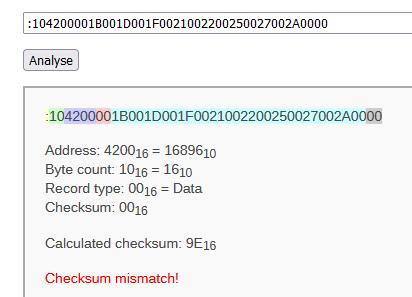
I’m unable to dig into a 10years old program but the workaround is simple :
Use an online checksum calculator and paste the faulty line :
https://www.fischl.de/hex_checksum_calculator/ says CRC should be 9E instead of 00. Then modify the .HEX with notepad++